
Datasheet


TVP5150AM1
SLES209E–NOVEMBER 2007–REVISED OCTOBER 2011
www.ti.com
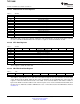
3.21.63 Interrupt Enable Register A
Address C1h
Default 00h
7 6 5 4 3 2 1 0
Reserved Lock interrupt Reserved FIFO threshold Line interrupt Data interrupt
enable interrupt enable enable enable
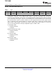
The interrupt enable register A is used by the host processor to mask unnecessary interrupt sources. Bits
loaded with a 1 allow the corresponding interrupt condition to generate an interrupt on the external pin.
Conversely, bits loaded with a 0 mask the corresponding interrupt condition from generating an interrupt
on the external pin. This register only affects the interrupt on the external terminal, it does not affect the
bits in interrupt status register A. A given condition can set the appropriate bit in the status register and not
cause an interrupt on the external terminal. To determine if this device is driving the interrupt terminal,
either perform a logical AND of interrupt status register A with interrupt enable register A, or check the
state of the interrupt A bit in the interrupt configuration register at address C2h.
Lock interrupt enable
0 = Disabled (default)
1 = Enabled
FIFO threshold interrupt enable
0 = Disabled (default)
1 = Enabled
Line interrupt enable
0 = Disabled (default)
1 = Enabled
Data interrupt enable
0 = Disabled (default)
1 = Enabled
66 Functional Description Copyright © 2007–2011, Texas Instruments Incorporated
Submit Documentation Feedback
www.ti.com: TVP5150AM1