
Datasheet


www.ti.com
S
2
C (Start-Stop Communication)
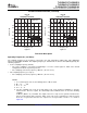
D15 D14 D13 D12 D11 D10 D9 D8 D7 D6 D5 D4 D3 D2 D1 D0
SCL
SDA
Start Bit = 0 Stop Bit = 1
SMARTDM Device
Address
(see Table 1)
Register
Address
Register Content
I
2
C
TLV320AIC12, TLV320AIC13
TLV320AIC14, TLV320AIC15
TLV320AIC12K, TLV320AIC14K
SLWS115E – OCTOBER 2001 – REVISED JANUARY 2007
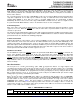
Table 1. SMARTDM Device Addresses (continued)
TOTAL CODEC POSITION IN CASCADE
CODECS
15 14 13 12 11 10 9 8 7 6 5 4 3 2 1 0
2 0001 0000
3 0010 0001 0000
4 0011 0010 0001 0000
5 0100 0011 0010 0001 0000
6 0101 0100 0011 0010 0001 0000
7 0110 0101 0100 0011 0010 0001 0000
8 0111 0110 0101 0100 0011 0010 0001 0000
9 1000 0111 0110 0101 0100 0011 0010 0001 0000
10 1001 1000 0111 0110 0101 0100 0011 0010 0001 0000
11 1010 1001 1000 0111 0110 0101 0100 0011 0010 0001 0000
12 1011 1010 1001 1000 0111 0110 0101 0100 0011 0010 0001 0000
13 1100 1011 1010 1001 1000 0111 0110 0101 0100 0011 0010 0001 0000
14 1101 1100 1011 1010 1001 1000 0111 0110 0101 0100 0011 0010 0001 0000
15 1110 1101 1100 1011 1010 1001 1000 0111 0110 0101 0100 0011 0010 0001 0000
16 1111 1110 1101 1100 1011 1010 1001 1000 0111 0110 0101 0100 0011 0010 0001 0000
The S
2
C is a write-only interface selected by programming bits D1-D0 of control register 2 to 01. The SDA input
is normally in a high state, pulled low (START bit) to start the communication, and pulled high (STOP bit) after
the transmission of the LSB. SCLK and FS must be active during register programming. Figure 26 shows the
timing diagram of S
2
C. The S
2
C also supports a broadcast mode in which the same register of all devices in
cascade is programmed in a single write. To use S
2
Cs broadcast mode, execute the following steps:
1. Write 111 1000 1111 1111 after the start bit to enable the broadcast mode.
2. Write data to program control register as specified in Figure 26 with bits D14-D11 = XXXX (don't care).
3. Write 111 1000 0000 0000 after the start bit to disable the broadcast mode.
Figure 26. S
2
C Programming
• Each I
2
C read-from or write-to 'AIC1xs control register is given by index register address.
• Read/write sequence always starts with the first byte as I
2
C address followed by 0. During the second byte,
default/broadcast mode is set and the index register address is initialized. For write operation control register,
data to be written is given from the third byte onwards. For read operation, stop-start is performed after the
second byte. Now the first byte is I
2
C address followed by 1. From the second byte onwards, control register
data appears.
• Each time read/write is performed, the index register address is incremented so that next read/write is
performed on the next control register.
• During the first write cycle and all write cycles in the broadcast, only the device with address 0000 issues
ACK to the I
2
C.
28
Submit Documentation Feedback