
Datasheet


0h
TBR
(max)
TBCL0−1 TBCL0 0h
Timer Clock
Timer
Set TBIFG
Set TBCCR0 CCIFG
1h TBCL0−1 TBCL0 0h
0h
TBR
(max)
TBCL0
Timer_B Operation
www.ti.com
13.2.3.1 Up Mode
The up mode is used if the timer period must be different from TBR
(max)
counts. The timer repeatedly
counts up to the value of compare latch TBCL0, which defines the period, as shown in Figure 13-2. The
number of timer counts in the period is TBCL0+1. When the timer value equals TBCL0 the timer restarts
counting from zero. If up mode is selected when the timer value is greater than TBCL0, the timer
immediately restarts counting from zero.
Figure 13-2. Up Mode
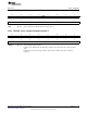
The TBCCR0 CCIFG interrupt flag is set when the timer counts to the TBCL0 value. The TBIFG interrupt
flag is set when the timer counts from TBCL0 to zero. Figure 13-3 shows the flag set cycle.
Figure 13-3. Up Mode Flag Setting
13.2.3.2 Changing the Period Register TBCL0
When changing TBCL0 while the timer is running and when the TBCL0 load event is immediate, CLLD0 =
00, if the new period is greater than or equal to the old period, or greater than the current count value, the
timer counts up to the new period. If the new period is less than the current count value, the timer rolls to
zero. However, one additional count may occur before the counter rolls to zero.
13.2.3.3 Continuous Mode
In continuous mode the timer repeatedly counts up to TBR
(max)
and restarts from zero as shown in
Figure 13-4. The compare latch TBCL0 works the same way as the other capture/compare registers.
Figure 13-4. Continuous Mode
The TBIFG interrupt flag is set when the timer counts from TBR
(max)
to zero. Figure 13-5 shows the flag set
cycle.
378
Timer_B SLAU144J–December 2004–Revised July 2013
Submit Documentation Feedback
Copyright © 2004–2013, Texas Instruments Incorporated