
Datasheet


Timer_A Registers
www.ti.com
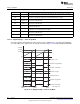
12.3.1 TACTL, Timer_A Control Register
15 14 13 12 11 10 9 8
Unused TASSELx
rw-(0) rw-(0) rw-(0) rw-(0) rw-(0) rw-(0) rw-(0) rw-(0)
7 6 5 4 3 2 1 0
IDx MCx Unused TACLR TAIE TAIFG
rw-(0) rw-(0) rw-(0) rw-(0) rw-(0) rw-(0) rw-(0) rw-(0)
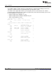
Unused Bits 15-10 Unused
TASSELx Bits 9-8 Timer_A clock source select
00 TACLK
01 ACLK
10 SMCLK
11 INCLK (INCLK is device-specific and is often assigned to the inverted TBCLK) (see the device-
specific data sheet)
IDx Bits 7-6 Input divider. These bits select the divider for the input clock.
00 /1
01 /2
10 /4
11 /8
MCx Bits 5-4 Mode control. Setting MCx = 00h when Timer_A is not in use conserves power.
00 Stop mode: the timer is halted.
01 Up mode: the timer counts up to TACCR0.
10 Continuous mode: the timer counts up to 0FFFFh.
11 Up/down mode: the timer counts up to TACCR0 then down to 0000h.
Unused Bit 3 Unused
TACLR Bit 2 Timer_A clear. Setting this bit resets TAR, the clock divider, and the count direction. The TACLR bit is
automatically reset and is always read as zero.
TAIE Bit 1 Timer_A interrupt enable. This bit enables the TAIFG interrupt request.
0 Interrupt disabled
1 Interrupt enabled
TAIFG Bit 0 Timer_A interrupt flag
0 No interrupt pending
1 Interrupt pending
370
Timer_A SLAU144J–December 2004–Revised July 2013
Submit Documentation Feedback
Copyright © 2004–2013, Texas Instruments Incorporated