270i This product is compliant with the applicable CE requirements.
Table of Contents Important Safety Instructions - Assembly 3 Safety Warning Labels / Serial Number 4 Specifications 5 Before Assembly 5 Parts 6 Hardware 7 Tools 7 Assembly 8 Moving the Machine 17 Leveling the Machine 18 Important Safety Instructions 19 Features 20 Console Features 21 Operations 26 Adjustments 26 Power Up / Idle Mode 26 Quick Start Program 27 User Profiles 27 Pausing or Stopping 32 Results / Cool Down Mode 32 GOAL TRACK Statistics 33
Important Safety Instructions -Assembly This icon means a potentially hazardous situation which, if not avoided, could result in death or serious injury. Obey the following warnings: Read and understand all warnings on this machine. Carefully read and understand the Assembly instructions. • Keep bystanders and children away from the product you are assembling at all times. • Do not connect power supply to the machine until instructed to do so.
Safety Warning Labels and Serial Number Serial Number Product Specifications • Read, understand and obey all warnings on this machine. • Keep children away. • Not intended for use by anyone under 14 years of age. • Prior to use, read and understand the Owner’s Manual. • Injury or death is possible if Caution is not used while using this machine. • The maximum user weight for this machine is 300 lbs (136 kg). • Replace any “Caution”, “Warning” or “Danger” label that is illegible, damaged, or removed.
Specifications Maximum User Weight: Machine Weight: 133.3 cm ( 52.5” ) 136 kg ( 300 lbs. ) 39.3 kg ( 86.6 lbs. ) Total Surface Area (foot print) of equipment: 10705.5 cm2 ( 1662.5 inches2 ) Power Requirements: Operational Voltage: 220V - 240V AC, 50Hz Operating Current: 0.4A 158.6 cm ( 62.5” ) 67.5 cm ( 26.6” ) Regulatory Approvals: This product conforms to the applicable EN ISO 20957 International Standards for Stationary Training Equipment, Class H.
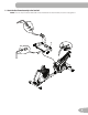
PARTS 17 2 1 3 5 16 6 15 4 14 7 13 8 9 12 Item Qty 1 1 2 6 Description 10 11 Item Qty Description Console 10 1 AC Adapter 1 Water Bottle Holder 11 1 Left Pedal 3 1 Seat Back 12 1 Front Stabilizer 4 1 Seat Cover 13 1 Right Pedal 5 1 Seat Frame Assembly 14 1 Upper Shroud 6 1 Seat Bottom 15 1 Shroud Cap 7 1 Seat Adjustment Handle 16 1 Console Mast 8 1 Rear Stabilizer 17 1 MP3 Cord 9 1 Frame
HARDWARE / TOOLs A Item Qty A 8 B B C D Description E F G H I Item Qty Button Head Hex Screw, M8x20 F 2 Phillips Head Screw, M5x12 10 Button Head Hex Screw, M6x12 G 14 Lock Washer, M6 C 4 Flat Washer, M8 H 4 Curved Washer, M6 D 8 Lock Washer, M8 I 4 Phillips Head Screw, M6x25 E 10 Flat Washer, M6 J 4 Curved Washer, M8 J Description Tools Included 4 mm 6 mm 7
ASSEMBLY 1. Attach StabilizerS to Frame Note: Hardware is pre-installed and not on the Hardware Card.
2. Attach the Seat Frame Assembly to the Seat Rail NOTICE: Do not crimp the Heart Rate Cable. Once all hardware has been inserted, be sure to fully tighten it.
3.
4. Attach Cover to Frame Assembly 4 5.
6. Connect the Cables and Attach the Console Mast to Frame Assembly NOTICE: Do not crimp Console Cables.
7. Remove Hardware from Console NOTICE: Do not crimp the cable. Note: Hardware is pre-installed and not on the Hardware Card. * 1 X4 * #2 8. Connect Cables and Attach Console to Frame Assembly NOTICE: Align the clips on the cable connectors and make sure the connectors lock. Do not crimp cables.
9. Attach Pedals to Frame Assembly NOTICE: The Left Pedal is reverse-threaded. Be sure to attach Pedals on the proper side of the Bike. Orientation is based from a seated position on the bike. The Left Pedal has an “L”, the Right Pedal an “R”.
10.
11. Connect AC Adapter to Frame Assembly 10 12. Final Inspection Inspect your machine to ensure that all hardware is tight and components are properly assembled. Be sure to record the serial number in the field provided at the front of this manual. Do not use until the machine has been fully assembled and inspected for correct performance in accordance with the Owner’s Manual.
BEFORE YOU START Moving the Machine The machine may be moved by one or more persons depending on their physical abilities and capacities. Make sure that you and others are all physically fit and able to move the machine safely. 1. Remove the power cord. 2. Use the Transport Handle to carefully lift the machine onto the transport rollers. 3. Push the machine into position. 4. Carefully lower the machine into position. NOTICE: Be careful when you move the bike.
Leveling the Machine Levelers are found on each side of the Rear Stabilizer and on the Frame Rail. On the Rear Stabilizer, turn the knob to adjust the stabilizer foot. Do not adjust the levelers to such a height that they detach or unscrew from the machine. Injury to you or damage to the machine can occur. To adjust the leveler on the Frame Rail: 1. Loosen the upper locking nut. 2. Turn the leveler to adjust the height.
Important Safety Instructions This icon means a potentially hazardous situation which, if not avoided, could result in death or serious injury. Before using this equipment, obey the following warnings: Read and understand the complete Manual. Keep the Manual for future reference. ead and understand all warnings on this machine. If at any time the Warning stickers become loose, unreadable or R dislodged, contact your local Schwinn® distributor for replacement stickers.
FEATURES C S T B A D P Q R E N F G M H I O L G F J A Console K Transport Wheel B MP3 Input L Fully Shrouded Flywheel C USB Port M Pedal D Water Bottle Holder N Storage Bin E Transport Handle O Seat Adjustment Handle F Stabilizer P Handlebar, Upright G Leveler Q Speakers H Handlebar, Side R Fan I Contact Heart Rate (CHR) Sensors S Media Tray J Power Connector T Telemetry Heart Rate (HR) Receiver ! WARNING WARNING indicates a hazardous Heart rate monito
Console Features The Console provides important information about your workout and lets you control the resistance levels while you exercise. The Console features the Schwinn Dual Track™ display with touch control buttons to navigate you through the exercise programs.
Achievement Indicator Lights- when an achievement level is reached or a result is reviewed, the achievement indicator light will activate. Schwinn Dual Track™ Display Upper Display Data Program Display 10 9 8 7 6 5 4 3 2 1 10% User Display Achievement Display Program Display The Program Display shows information to the User and the grid display area shows the course profile for the program. Each column in the profile shows one interval (workout segment).
0% 10% Lower Display Data PAUSE/ END 40% 70% Hr The Lower Display shows the Workout Values. and can be customized for each User (Consult the “Edit User Profile” section 25 of this manual). GOAL TRACK Speed 18 12 The Speed display field shows the machine speed in miles per hour (mph) or kilometers per hour (km/h).
Remote Heart Rate Monitor Monitoring your Heart Rate is one of the best procedures to control the intensity of your exercise. Contact Heart Rate (CHR) sensors are installed to send your heart rate signals to the Console. The Console can also read telemetry HR signals from a Heart Rate Chest Strap Transmitter that operates in the 4.5kHz - 5.5kHz range. Note: The heart rate chest strap must be an uncoded heart rate strap from Polar Electro or an uncoded POLAR® compatible model.
The most efficient procedure to burn fat during exercise is to start at a slow pace and gradually increase your intensity until your heart rate reaches between 60 – 85% of your maximum heart rate. Continue at that pace, keeping your heart rate in that target zone for over 20 minutes. The longer you maintain your target heart rate, the more fat your body will burn. The graph is a brief guideline, describing the generally suggested target heart rates based on age.
Operations What to Wear Wear rubber-soled athletic shoes. You will need the appropriate clothes for exercise that allow you to move freely. How Often Should You Exercise Consult a physician before you start an exercise program. Stop exercising if you feel pain or tightness in your chest, become short of breath, or feel faint. Contact your doctor before you use the machine again. Use the values calculated or measured by the machine’s computer for reference purposes only.
Initial Setup During the first power-up, the Console should be setup with the date, time and your preferred measurement units. 1. D ate: Push the Increase/Decrease buttons to adjust the currently active value (flashing). Push the Left/Right buttons to change which segment is the currently active value (month / day / year). 2. Push OK to set. 3. T ime: Push the Increase/Decrease buttons to adjust the currently active value (flashing).
Select a User Profile Every workout is saved to a User Profile. Be sure to select the proper User Profile before starting a workout. The last User that completed a workout will be the default user. User Profiles are assigned the default values until they are customized by editing. Be sure to edit the User Profile for more accurate calorie and heart rate information. From the Power-Up Mode screen, push the Increase() or Decrease() buttons to select one of the User Profiles.
Hr 9. The Console will go to the Power-Up Mode screen with the user selected. Reset a User Profile 1. From the Power-Up Mode screen, push the Increase() or Decrease() buttons to select one of the User Profiles. 2. Push the OK button to select the User Profile. 3. T he Console display shows the current User Profile name and the EDIT prompt. Push the Increase() or Decrease() buttons to change the prompt.
Rolling Hills Ride in the Park Ride in the Park Easy Tour Easy Tour Stream Crossing Ride in the Park Stream Crossing Ride in the Park Stream Crossing Easy Tour Easy Tour Stream Crossing Mount Hood Mount Hood Mount Hood Pyramids Pyramids Summit Pass Mount Hood Pyramids Pyramids Summit Pass Cross-Training Interval Interval Stairs Interval Interval Stairs FUN RIDES FUN RIDES Rolling Hills Easy Tour CHALLENGES MOUNTAINS Pike’s Peak Pyramids Pyramids Uphill Finish Uphill Fini
Fitness Test Program The Fitness Test measures the improvements of your physical fitness level. The test compares your power output (in Watts) to your heart rate. As your fitness level improves, your power output will increase at a given heart rate. Note: The Console must be able to read the heart rate information from the Contact Heart Rate (CHR) sensors or Heart Rate Monitor (HRM) to work correctly. You can start the Fitness Test from the FEEDBACK category.
The Target Heart Rate programs use your age and other User information to set the Heart Rate Zone values for your workout. The console display then gives prompts for you to set up your workout: 1. Select the Heart Rate Control workout level: BEGINNER ( “BEG” ) or ADVANCED ( “ADV” ) and push OK. 2. P ush the Increase() or Decrease() buttons to select the percentage of maximum heart rate: 50–60%, 60–70%, 70– 80%, 80–90%. Consult a physician before you start an exercise program.
- PUSH END TO STOP During a paused workout, you can use the Increase/Decrease buttons to move through the result channels manually. 1. Stop pedaling and push the PAUSE/END button to pause your workout. 2. To continue your workout, push OK or start pedaling. To stop the workout, push the PAUSE/END button. The Console will go into Results / Cool Down mode. Results / Cool Down Mode After a workout the GOAL display shows 03:00 and then starts to count down.
4. P ush the Increase() button to move to “LAST 30 DAYS”. The Console will display the total values for the previous thirty days. Use the Left() or Right() buttons to move through all the workout statistic channels. 5. P ush the Increase() button to move to the “LONGEST WORKOUT”. The Console will display the workout values with the most Time value. Use the Left() or Right() buttons to move through all the workout statistic channels. 6.
CONSOLE SETUP MODE The Console Setup Mode lets you input the date and time, set the units of measurement to either English or Metric, change the machine type, control the sound settings ( on/ off), or see maintenance statistics (Error Log and Run Hours – for service technician use only). 1. H old down the PAUSE/END button and Right button together for 3 seconds while in the Power-Up Mode to go into the Console Setup Mode.
MAINTENANCE Read all maintenance instructions fully before you start any repair work. In some conditions, an assistant is required to do the necessary tasks. Equipment must be regularly examined for damage and repairs. The owner is responsible to make sure that regular maintenance is done. Worn or damaged components must be repaired or replaced immediately. Only manufacturer supplied components can be used to maintain and repair the equipment.
Maintenance Parts A B CC C D AA BB Z E F Y X G H V W N U M O T P I L K S R J Q 37
A Console K Shroud, Left U Speed Sensor Magnet B Seat Back L Transport Wheel V Console Cable, Lower C Seat Cover M Stabilizer, Front W Shroud, Right D Water Bottle Holder N Heart Rate Cable, Lower X Pedal, Right E Handlebar, Side O Speed Sensor Y Shroud, Upper F Seat Bottom P Crank Arm Z Shroud Cap G Seat Adjustment Handle Q Servo Motor AA Console Cable, Upper H Frame Assembly R Brake Assembly BB Heart Rate Cable, Upper I Rear Stabilizer S Flywheel CC Con
Troubleshooting Condition/Problem No display/partial display/ unit will not turn on Things to Check Solution Check electrical (wall) outlet Make sure unit is plugged into a functioning wall outlet. Check connection at front of unit Connection should be secure and undamaged. Replace adapter or connection at unit if either are damaged. Check data cable integrity All wires in cable should be intact. If any are visibly crimped or cut, replace cable.
No speed/RPM reading, Console displays “Please Pedal” error code Check data cable integrity All wires in cable should be intact. If any are cut or crimped, replace cable. Check data cable connections/orientation Be sure cable is connected securely and oriented properly. Small latch on connector should line up and snap into place. Check magnet position (requires shroud removal) Magnet should be in place on pulley.
EN Nautilus® 8003249.090113.