
Datasheet


www.keithley.com
1.888.KEITHLEY (U.S. only)
A GREATER MEASURE OF CONFIDENCE
Model 7701 Specifications
SWITCH/MEASURE SYSTEMS
25
Integra Series Multimeter/Switch Systems
Modules
7701 LOW-VOLTAGE 32-CHANNEL
DIFFERENTIAL MULTIPLEXER
FEATURES
• Configurable for 32 channels of differential measurements, with up to 16 channels
of 4-pole measurements.
• Configurable for 32 channels of common-side 4-wire ohms.
• Configurable as two independent banks of multiplexers.
•Two female D-shell connectors are standard for secure hook-up and
quick teardown.
• 150V, 1A capacity for voltage channels; 60W, 125VA.
•Two mating IDC connectors for ribbon cable are supplied.
• Relay closures stored in on-board memory.
• Screw terminal jumpers allow user-configurable DMM connections.
GENERAL
32 CHANNELS: 32 channels of 2-pole relay input. All channels configurable to 4-pole.
RELAY TYPE: Latching electromechanical.
ACTUATION TIME: <3ms.
FIRMWARE: Specified for Model 2700 rev. B03, Model 2701 rev. A01, and Model 2750
rev. A01 or higher.
DMM CONNECTIONS: Screw terminals provide internal DMM connections to chan-
nels 34 and 35 and connections to external wiring access.
CAPABILITIES
CHANNELS 1–32: Multiplex one of 32 2-pole or one of 16 4-pole signals into DMM.
Configuration supports dual 1×16 independent multiplexers.
INPUTS
MAXIMUM SIGNAL LEVEL: Any channel to Any Channel (1–32): 150V DC or
150Vrms (212V peak) for AC waveforms, 1A switched, 60W, 125VA maximum.
SAFETY: Conforms to European Union Directive 73/23/EEC EN61010-1, CAT I.
CONTACT LIFE (typ): >10
5
operations at max signal level.
>10
8
operations cold switching.
CONTACT RESISTANCE: <1Ω any path and additional 1Ω at end of contact life.
CONTACT POTENTIAL: <6µV per contact pair.
OFFSET CURRENT: <100pA.
CONNECTOR TYPE: 50-pin female D-shell, Channels 1–24.
25-pin female D-shell, Channels 25–32.
Supplied with male IDC ribbon cable connectors.
ISOLATION BETWEEN ANY TWO TERMINALS: >10
9
Ω, <200pF.
ISOLATION BETWEEN ANY TERMINAL AND EARTH: >10
9
Ω, <400pF.
CROSS TALK (1MHz, 50Ω Load): <–35dB.
INSERTION LOSS (50Ω Source, 50Ω Load): <0.35dB below 1MHz.
<3dB below 2MHz.
COMMON MODE VOLTAGE: 300VDC or 300Vrms (425V peak) for AC waveforms
between any terminal and chassis.
ENVIRONMENTAL:
OPERATING ENVIRONMENT: Specified for 0°C to 50°C.
Specified to 50% R.H. at 35°C.
STORAGE ENVIRONMENT: –25°C to 65°C.
WEIGHT: <0.52kg (1.16 lb).
ACCESSORIES AVAILABLE:
Model 7789 50/25 Pin Male D-Shell Solder Cup Connectors
Model 7790 50/50/25 Pin Female/Male D-Shell IDC Connectors
Model 7705-MTC-2 50 Pin Male to Female DSUB Cable, 2m (6.6 ft).
Model 7707-MTC-2 25 Pin Male to Female DSUB Cable, 2m (6.6 ft).
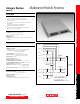
Channel 1
HI
LO
Channel 16
HI
LO
(Channels 2–15)
Channel 17
HI
LO
Channel 32
HI
LO
(Channels 18–31)
Backplane
Isolation
HI
LO
Backplane
Isolation
HI
LO
DMM Input
Channel 33
2-Pole (Open)
4-Pole (Closed)
(see Note)
To
Internal
DMM
NOTE Channels 33–35 in this schematic refer to the designations
used for control and not actual available channels.
For more information, refer to the ROUTE:MULT command
section in the Model 2700, 2701, or 2750 User’s Manual.
Channel 35
(see Note)
Channel 34
(see Note)
Multiplexer 1
HI
LO
Screw
Terminals
Screw
Terminals
The Model 7701 is rated for low-voltage applications.
When connecting the 7701 to the internal DMM via
the screw terminals, all other modules in the
mainframe must be derated to 150VDC or 150Vrms
(212V peak) for AC waveforms.
HI
LO
HI
LO
DMM Sense
Multiplexer 2
HI
LO
External
Wiring Access
User
Configurable
Screw
Terminals
See page 43 for common-side 4-wire ohms configuration example.