
Service Manual


SECTION
3
IGNITION
operation
The firing of the spark plug at the proper time
is
the
culmination of a number of components working together.
These components on the GTS 150 are:
Flywheel
Ignition armature coil
Spark plug
Armature coil wiring
The following describes the function of each of the above
components.
Ignition
Operation
-
Flywheel
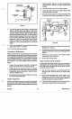
The flywheel is connected directly to the crankshaft and
turns at the same speed
as
the crankshaft. Imbedded in
the flywheel are three magnets. These magnets rotate
past the coil to generate electricity.
Imbedded in the opposite side of the flywheel are steel
counterweights which offset the weight of the three mag-
nets. These counterweights are not magnetic.
Ignition Operation
-
Ignition
Armature Coil
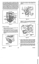
The ignition armature coil is actually a transformer.
It
is
positioned close to the flywheel to allow the magnetic field
of the flywheel magnets to cut through the wire coils of the
armature coil to generate electricity. See Figure 21.
IGNITION
COIL
Figure
21
Complete operation of the ignition circuit is described with
reference to Figure 22.
GTS
150
25
Figure
22
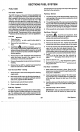
Lowvoltage is produced in the primary coil of the armature
coil which causes a very small current to flow through
resistor
"R"
to the base of transistor TR1. This small base
current will cause the transistor to "turn on" creating a low
resistance path through the collector, emitter circuit of the
transistor
as
shown by the dotted line.
As the magnets continue to cut through the coils of the
primary winding the primary voltage will increase.
This
voltage also develops across the voltage divider network
created by resistors R1
,
R2. At a precisely timed moment,
the voltage at point
"A"
turns TR2 "on" creating
a
low
resistance path for the base current flowing through resis-
tor
"R".
In fact, when this occurs,
it
is easier for the current
to flow through the collector, emitter circuit of TR2 than it
is
through the base, emitter circuit of TR1.
With the base current for TRI diverted, TR1 turns
"off,
opening the armature coil primary circuit. Remember, the
current flowing through resistor
"R"
and TR2 is extremely
small and can not support the magnetic field created
in
the
primary winding. When the circuit through TR1 opens, the
magneticfield in the primary winding collapses, generating
an extremely high voltage in the secondary winding,
enough voltage to cause a spark at the spark plug.
Ignition Operation Spark Plug
The spark plug is used to ignite the air-fuel mixture by
producing a spark just before the piston reaches top dead
center. A spark plug is typically constructed
as
shown
in
Figure
23.
Ignition