
Service Manual


SECTION
2
FUEL
SYSTEM
FUEL
TANK
Fuel lank Operation
The GTS150 uses a 1.6 quart (1.5 liters) plastic fuel tank
with a non-replaceable75micron in-tankfilterscreen. The
filter is welded in the bottom of the tank over a sediment
reservoir. The tank is mounted above the level of the
carburetor and uses gravity to supply fuel through a .25'
I.D. (6.35 mm) rubber hose to the carburetor. The fuel tank
is vented through an opening in the fuel cap. The fuel hose
is retained to the tank and the carburetor with spring type
hose clamps. The fuel opening on the tank is 1.75" (45
mm) in diameter and is opposite the fuel outlet helping to
prevent damage to the filter screen by funnels and gaso-
line filler spouts. The placement of the cap also prevents
interference with the starting rope
in
Zone
Start
applications.
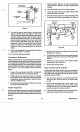
Fuel lank Removal
1. Crimp the fuel hose with a pair of locking pliers to
2. Remove the hose clamp on the carburetor end of the
3.
CAUTION:
Avoid fire and explosion. Store fuel
in a container designed for gasoline and never smoke
while working around gasoline. Release the clamping
pliers and drain the fuel into a container designed to
receive gasoline.
4. Remove the four 3/8" hex, washer head screws that
retain the blower housing to the engine. It is not
necessary to remove the recoil starter.
5. Remove the gasoline tank cap and remove the blower
housing.
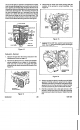
6.
Remove the
two
3/8" hex, washer head screws that
retain the fuel tank to the fuel tank bracket.
prevent fuel flow.
hose.
Fuel lank and Filter Cleanlng
1. Wash the tank in clean solvent designed for cleaning
engine parts.
2. Back wash the filter screen by directing cleaning
sol-
vent, under pressure, through the sediment reservoir
and screen, opposite fuel flow direction.
3. Wash the tank again with clean solvent.
4. Clean or replace the fuel hose.
Fuel Cap Operation
The fuel cap is a three piece design with an inner sealing
disc that is vented to a baffle assembly in the body of the
cap. The baffle assembly acts to allow expansion in the
tank without
loss
of fuel. Atmospheric pressure is allowed
GTS150
23
into the tank from an opening in the cap to allow gravity to
feed fuel to the carburetor.
Fuel Cap Service
1.
The fuel cap may not
be
disassembled, however, the
vent opening on the cap and inner sealing disc should
be kept free of debris.
2. Theventilating ability of the cap may be tested by filling
the cap with water and observing the flow
of
water out
of the vent opening
in
the side of the cap. If water does
not drain,
the
vent
opening may
be
plugged
or
restricted
3.
If the cap will not vent properly,
it
should be replaced.
Fuel Hose
-
Removal
1.
CAUTION:
Avoid fire and explosions. Store
fuel
in
a container designed for gasoline and never
smoke while working around gasoline.
2. Remove the air cleaner cover and foam element.
3.
Remove the three 5/16" hex, washer head shoulder
screws that retain the air cleaner body to the engine.
4. Pull the air cleaner body away from the engine. Take
care not to lose the cork gasket between the air
cleaner and the carburetor. Take note of the position
of the breather hose on the back of the air cleaner and
the location of its' connection to the breathervent tube.
5.
Disconnect the fuel hose from the carburetor by
squeezing the spring type hose clamp with a pair of
pliers.
6.
Drain the fuel into a container designed for gasoline.
7.
Remove the fuel hose from the fitting on the bottom of
the gasoline tank.
Fuel Hose
-
Installation
1.
2.
3.
4.
Make certain the fuel hose is clean. Even
if
the fuel
hose is new, run clean solvent through the inside of the
hose prior to installation.
Install
a
spring type hose clamp
2"
(5 cm) from each
end of the fuel hose. Install the hose on the outlet pipe
of the fuel tank. Secure the fuel hose with the hose
clamp.
Install the other end of the fuel hose to the inlet pipe on
the carburetor and secure it with the remaining hose
clamp.
Install the body of the air cleaner.
IMPORTANT:
Take care that the breather vent hose
on the back of the air cleaner body mates with the
Fuel
System