
Datasheet


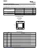


OUT
NC
NC
NC
IN
1
2
3
4
5
6
20
7
19
8
18
9
17
10
16
15
14
13
12
11
OUT
IN
NR
EN
0P1V
0P2V
3P2V
GND
1P6V
0P8V
0P4V
NC
SENSE/FB
6P4V2
6P4V1
(Thermal Pad)
TPS7A4700
TPS7A4701
SBVS204E –JUNE 2012–REVISED JANUARY 2014
www.ti.com
ELECTRICAL CHARACTERISTICS (continued)
At –40°C ≤ T
J
≤ +125°C; V
IN
= V
OUT(NOM)
+ 1.0 V or V
IN
= 3.0 V (whichever is greater); V
EN
= V
IN
; I
OUT
= 0 mA; C
IN
=10 µF;
C
OUT
= 10 µF; C
NR
= 10 nF; SENSE/FB tied to OUT; and 0P1V, 0P2V, 0P4V, 0P8V, 1P6V, 3P2V, 6P4V1, 6P4V2 pins OPEN,
unless otherwise noted.
PARAMETER TEST CONDITIONS MIN TYP MAX UNIT
V
IN
= 3 V, V
OUT(NOM)
= 1.4 V, C
OUT
= 50 µF,
4.17 µV
RMS
C
NR
= 1 µF, BW = 10 Hz to 100 kHz
V
NOISE
Output noise voltage
V
IN
= 6 V, V
OUT(NOM)
= 5 V, C
OUT
= 50 µF,
4.67 µV
RMS
C
NR
= 1 µF, BW = 10 Hz to 100 kHz
V
IN
= 16 V, V
OUT(NOM)
= 15 V, C
OUT
= 50 µF,
PSRR Power-supply rejection ratio 78 dB
I
OUT
= 500 mA, C
NR
= 1 µF, f = 1 kHz
T
J
Operating junction temperature –40 +125 °C
Shutdown, temperature increasing +170 °C
T
SD
Thermal shutdown temperature
Reset, temperature decreasing +150 °C
PIN CONFIGURATIONS
RGW PACKAGE
5-mm × 5-mm QFN-20
(TOP VIEW)
PIN DESCRIPTIONS
PIN
PIN NAME NUMBER DESCRIPTION
When connected to GND, this pin adds 0.1 V to the nominal output voltage of the regulator.
0P1V 12
Do not connect any voltage other than GND to this pin. If not used, leave this pin floating.
When connected to GND, this pin adds 0.2 V to the nominal output voltage of the regulator.
0P2V 11
Do not connect any voltage other than GND to this pin. If not used, leave this pin floating.
When connected to GND, this pin adds 0.4 V to the nominal output voltage of the regulator.
0P4V 10
Do not connect any voltage other than GND to this pin. If not used, leave this pin floating.
When connected to GND, this pin adds 0.8 V to the nominal output voltage of the regulator.
0P8V 9
Do not connect any voltage other than GND to this pin. If not used, leave this pin floating.
When connected to GND, this pin adds 1.6 V to the nominal output voltage of the regulator.
1P6V 8
Do not connect any voltage other than GND to this pin. If not used, leave this pin floating.
When connected to GND, this pin adds 3.2 V to the nominal output voltage of the regulator.
3P2V 6
Do not connect any voltage other than GND to this pin. If not used, leave this pin floating.
When connected to GND, this pin adds 6.4 V to the nominal output voltage of the regulator.
6P4V1 5
Do not connect any voltage other than GND to this pin. If not used, leave this pin floating.
When connected to GND, this pin adds 6.4 V to the nominal output voltage of the regulator.
6P4V2 4
Do not connect any voltage other than GND to this pin. If not used, leave this pin floating.
Enable pin. The device is enabled when the voltage on this pin exceeds the maximum enable voltage,
EN 13
V
EN(HI)
. If enable is not required, tie EN to IN.
4 Submit Documentation Feedback Copyright © 2012–2014, Texas Instruments Incorporated
Product Folder Links: TPS7A4700 TPS7A4701