
Datasheet


www.ti.com
THEORY OF OPERATION
ADC SECTION
1
st
SW-CAP
Integrator
Analog
In
X(z)
+
−
+
−
2
nd
SW-CAP
Integrator
3
rd
SW-CAP
Integrator
+
−
4
th
SW-CAP
Integrator
+
+
+
+
+
+
+
+
5
th
SW-CAP
Integrator
Digital
Out
Y(z)
Comparator
Qn(z)
H(z)
1-Bit
DAC
STF(z) = H(z) / [1 + H(z)]
NTF(z) = 1 / [1 + H(z)]
Y(z) = STF(z) * X(z) + NTF(z) * Qn(z)
Signal Transfer Function
Noise Transfer Function
B0005-02
DAC SECTION
PCM3052A
SLES160 – NOVEMBER 2005
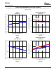
The ADC block consists of a reference circuit, two channels of single-ended to differential converter, a fifth-order
delta-sigma modulator with fully differential architecture, a decimation filter with high-pass filter, and a serial
interface circuit which is also used as the serial interface for the DAC input signal as shown in the block diagram.
Figure 39 is the block diagram of the fifth-order delta-sigma modulator and transfer function.
An on-chip reference circuit with two external capacitors provides all reference voltages that are needed in the
ADC section, and defines the full-scale voltage range of both channels.
An on-chip, single-ended to differential signal converter saves the design, space, and extra parts cost of an
external signal converter.
Full differential architecture provides a wide dynamic range and excellent power supply rejection performance.
The input signal is sampled at × 64 oversampling rate and an on-chip antialiasing filter eliminates the need for an
external sample-hold amplifier. A fifth-order delta-sigma noise shaper, which consists of five integrators using the
switched-capacitor technique and a comparator, shapes the quantization noise generated outside of audio signal
band by the comparator and 1-bit DAC.
The high-order delta-sigma modulation randomizes the modulator outputs and reduces idle-tone level.
The 64 f
S
, 1-bit stream from the delta-sigma modulator is converted to a 1-f
S
, 24-bit digital signal by removing
high-frequency noise components with the decimation filter.
The dc component of the signal is removed by the HPF, and the HPF output is converted to a time-multiplexed
serial signal through the serial interface.
Figure 39. Block Diagram of Fifth-Order Delta-Sigma Modulator
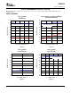
The DAC section is based on the delta-sigma modulator, which consists of an 8-level amplitude quantizer and a
fourth-order noise shaper. This section converts the oversampled input data to 8-level delta-sigma format. A
block diagram of the 8-level delta-sigma modulator is shown in Figure 40 . This 8-level delta-sigma modulator has
the advantage of stability and clock jitter over the typical one-bit (2-level) delta-sigma modulator. The combined
oversampling rate of the delta-sigma modulator and the internal 8 × interpolation filter is 64 f
S
for all system
clocks. The theoretical quantization-noise performance of the 8-level delta-sigma modulator is shown in
Figure 41 .
20