
Datasheet


MAX17030/MAX17036
1/2/3-Phase Quick-PWM
IMVP-6.5 VID Controllers
22 ______________________________________________________________________________________
where L
ESL
is the equivalent series inductance of the cur-
rent-sense resistor, R
SENSE
is current-sense resistance
value, and C
EQ
and R
EQ
are the time-constant matching
components.
Current Balance
The MAX17030/MAX17036 integrate the difference
between the current-sense voltages and adjust the on-
time of the secondary phase to maintain current bal-
ance. The current balance relies on the accuracy of the
current-sense signals across the current-sense resistor
or inductor DCR. With active current balancing, the cur-
rent mismatch is determined by the current-sense resis-
tor or inductor DCR values and the offset voltage of the
transconductance amplifiers:
where R
SENSE
= R
CM
= R
CS
and V
OS(IBAL)
is the
current balance offset specification in the
Electrical
Characteristics
table.
The worst-case current mismatch occurs immediately
after a load transient due to inductor value mismatches
resulting in different di/dt for the two phases. The time it
takes the current-balance loop to correct the transient
imbalance depends on the mismatch between the
inductor values and switching frequency.
III
V
R
OS IBAL LMAIN LSEC
OS IBAL
SENSE
()
()
=−=
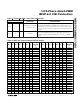
A) OUTPUT SERIES RESISTOR SENSING
DH_
INPUT (V
IN
)
DL_
LX_
C
IN
N
L
N
H
D
L
CSP_
CSN_
L
B) LOSSLESS INDUCTOR SENSING
DH_
INPUT (V
IN
)
DL_
LX_
C
IN
N
L
N
H
D
L
CSP_
CSN_
C
OUT
INDUCTOR
R1
C
EQ
L
R
DCR
SENSE RESISTOR
L
ESL
R
SENSE
C
OUT
R
EQ
C
EQ
R2
R
SENSE
L
ESL
C
EQ
R
EQ
=
R
DCR
R1 + R2
R2
R
CS
=
11
R1 R2C
EQ
L
R
DCR
=
[
+
]
FOR THERMAL COMPENSATION:
R2 SHOULD CONSIST OF AN NTC RESISTOR IN
SERIES WITH A STANDARD THIN-FILM RESISTOR
MAX17030
MAX17036
MAX17030
MAX17036
Figure 4. Current-Sense Methods