
Datasheet


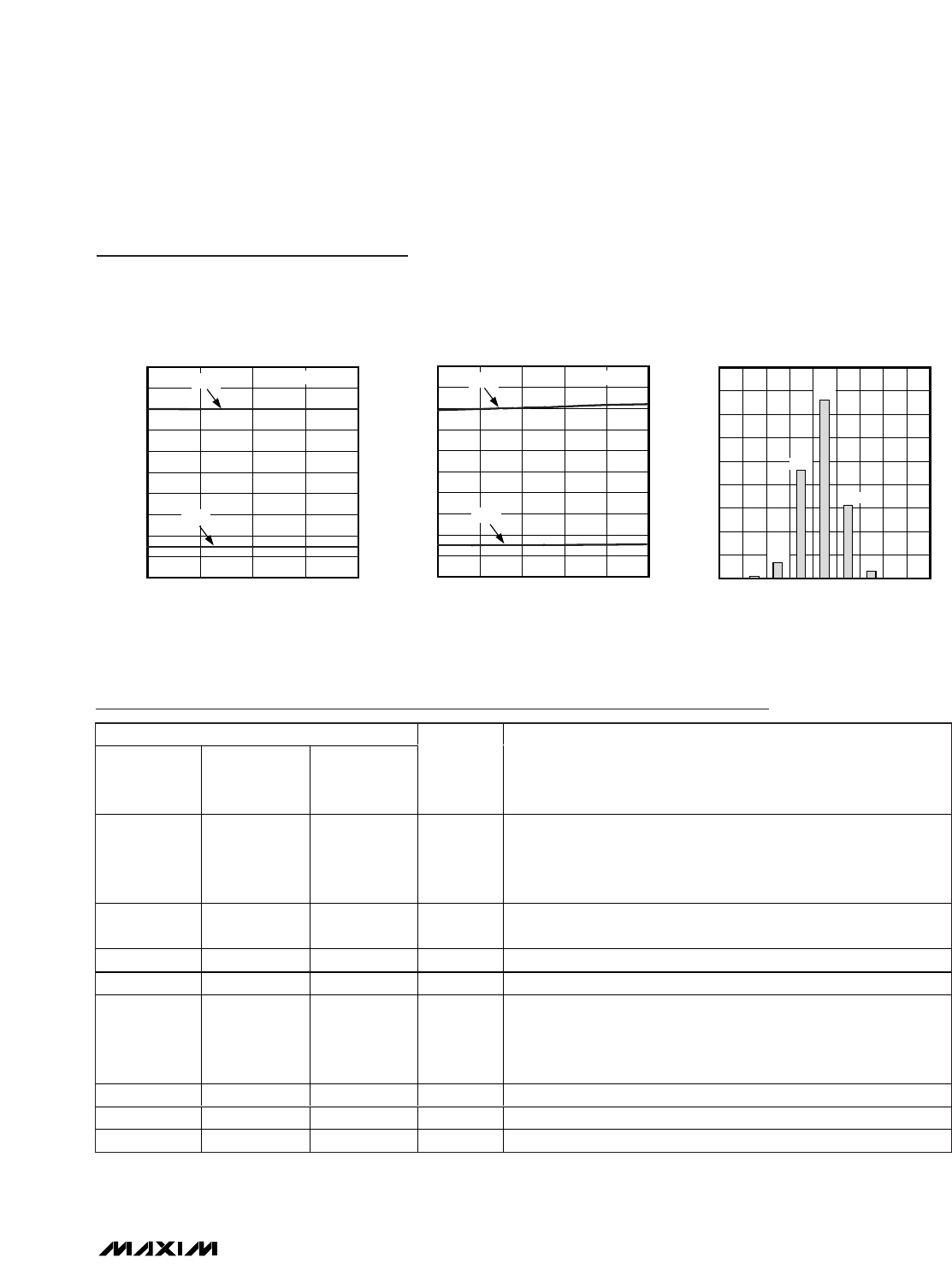
OUTPUT HISTOGRAM
(DC INPUT)
MAX1316 toc20
DIGITAL OUTPUT CODE
COUNTS
821782168214 82158211 8212 82138210
500
1000
1500
2000
2500
3000
3500
4000
4500
0
01013
8209
2306
1562
154
341
3815
CONVERSION TIME
vs. TEMPERATURE
MAX1316 toc19
TEMPERATURE (°C)
CONVERSION TIME (µs)
603510-15
0.2
0.4
0.6
0.8
1.0
1.2
1.4
1.6
1.8
2.0
0
-40 85
t
NEXT
t
CONV
INTERNAL CLOCK
CONVERSION TIME
vs. ANALOG SUPPLY VOLTAGE
MAX1316 toc18
ANALOG SUPPLY VOLTAGE (V)
CONVERSION TIME (µs)
5.1255.0004.875
0.2
0.4
0.6
0.8
1.0
1.2
1.4
1.6
1.8
2.0
0
4.750 5.250
t
NEXT
t
CONV
INTERNAL CLOCK
Typical Operating Characteristics (continued)
(AV
DD
= +5V, DV
DD
= +3V, AGND = DGND = 0V, V
REF
= V
REFMS
= +2.5V (external reference), see the
Typical Operating Circuits
sec-
tion, f
CLK
= 10MHz, 50% duty cycle, INTCLK/EXTCLK = AGND (external clock), SHDN = DGND, T
A
= +25°C, unless otherwise noted.)
MAX1316–MAX1318/MAX1320–MAX1322/MAX1324–MAX1326
8-/4-/2-Channel, 14-Bit, Simultaneous-Sampling ADCs
with ±10V, ±5V, and 0 to +5V Analog Input Ranges
_______________________________________________________________________________________
9
Pin Description
PIN
MAX1316
MAX1320
MAX1324
MAX1317
MAX1321
MAX1325
MAX1318
MAX1322
MAX1326
NAME FUNCTION
1, 15, 17 1, 15, 17 1, 15, 17 AV
DD
Analog Supply Input. AV
DD
is the power input for the analog section
of the converter. Apply 4.75V to 5.25V to AV
DD
. Bypass AV
DD
to
AGND (pin 14 to pin 15, pin 16 to pin 17, pin 1 to pin 2) with a 0.1µF
capacitor at each AV
DD
input.
2, 3, 14, 16, 23 2, 3, 14, 16, 23 2, 3, 14, 16, 23 AGND
Analog Ground. AGND is the power return for AV
DD
. Connect all
AGNDs together.
4 4 4 CH0 Channel 0 Analog Input
5 5 5 CH1 Channel 1 Analog Input
666MSV
Midscale Voltage Bypass. For the MAX1316/MAX1317/MAX1318,
connect a 2.2µF and a 0.1µF capacitor from MSV to AGND. For the
MAX1320/MAX1321/MAX1322/MAX1324/MAX1325/MAX1326,
connect MSV directly to AGND.
7 7 — CH2 Channel 2 Analog Input
8 8 — CH3 Channel 3 Analog Input
9 — — CH4 Channel 4 Analog Input