
Datasheet


"#$%&'
SBAS417B − JUNE 2007 − REVISED JANUARY 2008
www.ti.com
12
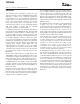
Converter
+IN
+REF
Y+
+V
CC
X+
Y
−
GND
−
REF
−
IN
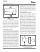
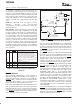
Figure 5. Simplified Diagram of Differential
Reference (SER/DFR low, Y switches enabled,
X+ is analog input)
As a final note about the differential reference mode, it
must be used with +V
CC
as the source of the +REF voltage
and cannot be used with V
REF
. It is possible to use a
high-precision reference on V
REF
and single-ended
reference mode for measurements that do not need to be
ratiometric. In some cases, it is possible to power the
converter directly from a precision reference. Most
references can provide enough power for the TSC2046E,
but might not be able to supply enough current for the
external load (such as a resistive touch screen).
TOUCH SCREEN SETTLING
In some applications, external capacitors may be required
across the touch screen for filtering noise picked up by the
touch screen (for example, noise generated by the LCD
panel or backlight circuitry). These capacitors provide a
low-pass filter to reduce the noise, but cause a settling time
requirement when the panel is touched that typically
shows up as a gain error. There are several methods for
minimizing or eliminating this issue. The problem is that
the input and/or reference has not settled to the final
steady-state value prior to the ADC sampling the input(s)
and providing the digital output. Additionally, the reference
voltage may still be changing during the measurement
cycle. Option 1 is to stop or slow down the TSC2046E
DCLK for the required touch screen settling time. This
option allows the input and reference to have stable values
for the Acquire period (3 clock cycles of the TSC2046E;
see Figure 9). This option works for both the single-ended
and the differential modes. Option 2 is to operate the
TSC2046E in the differential mode only for the touch
screen measurements and command the TSC2046E to
remain on (touch screen drivers ON) and not go into
power-down (PD0 = 1). Several conversions are made,
depending on the settling time required and the
TSC2046E data rate. Once the required number of
conversions have been made, the processor commands
the TSC2046E to go into its power-down state on the last
measurement. This process is required for X-Position,
Y-Position, and Z-Position measurements. Option 3 is to
operate in the 15 Clock-per-Conversion mode, which
overlaps the analog-to-digital conversions and maintains
the touch screen drivers on until commanded to stop by the
processor (see Figure 13).
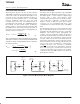
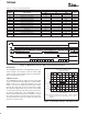
TEMPERATURE MEASUREMENT
In some applications, such as battery recharging, a
measurement of ambient temperature is required. The
temperature measurement technique used in the
TSC2046E relies on the characteristics of a
semiconductor junction operating at a fixed current level.
The forward diode voltage (V
BE
) has a well-defined
characteristic versus temperature. The ambient
temperature can be predicted in applications by knowing
the +25°C value of the V
BE
voltage and then monitoring the
delta of that voltage as the temperature changes. The
TSC2046E offers two modes of operation. The first mode
requires calibration at a known temperature, but only
requires a single reading to predict the ambient
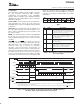
temperature. A diode is used (turned on) during this
measurement cycle. The voltage across the diode is
connected through the MUX for digitizing the forward bias
voltage by the ADC with an address of A2 = 0, A1 = 0, and
A0 = 0 (see Table 1 and Figure 6 for details). This voltage
is typically 600mV at +25°C with a 20µA current through
the diode. The absolute value of this diode voltage can
vary by a few millivolts. However, the temperature
coefficient (T
C
) of this voltage is very consistent at
–2.1mV/°C. During the final test of the end product, the
diode voltage would be stored at a known room
temperature, in memory, for calibration purposes by the
user. The result is an equivalent temperature
measurement resolution of 0.3°C/LSB (in 12-bit mode).
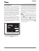
ADC
MUX
TEMP0 TEMP1
+V
CC
Figure 6. Functional Block Diagram of
Temperature Measurement