
Datasheet


TPS62230, TPS62231, TPS62232, TPS62233, TPS62234, TPS62235, TPS62236
TPS62237, TPS62238, TPS62239, TPS622310, TPS622311, TPS622312
TPS622313, TPS622314, TPS622315, TPS622316, TPS622317, TPS622318
www.ti.com
SLVS941E –APRIL 2009–REVISED DECEMBER 2010
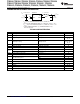
DISSIPATION RATINGS
(1)
POWER RATING DERATING FACTOR
PACKAGE R
θJA
FOR T
A
≤ 25°C ABOVE T
A
= 25°C
1 × 1.5 SON 234°C/W
(2)
420 mW 4.2 mW/°C
(1) Maximum power dissipation is a function of T
J(max)
, θ
JA
and T
A
. The maximum allowable power dissipation at any allowable ambient
temperature is P
D
= [T
J(max)
– T
A
] /
θJA
.
(2) This thermal data is measured with high-K board (4 layers board according to JESD51-7 JEDEC standard).
RECOMMENDED OPERATING CONDITIONS
operating ambient temperature T
A
= –40 to 85°C (unless otherwise noted)
(1)
MIN NOM MAX UNIT
Supply voltage V
IN
(2)
2.05 6 V
Effective inductance 2.2 μH
Effective capacitance 2.0 4.7 μF
V
OUT
≤ V
IN
-1 V
(3)
500 mA maximum I
OUT
(4)
3.0 3.6
Recommended minimum
350mA maximum I
OUT
(5)
2.5 2.7 V
supply voltage
V
OUT
≤ 1.8V 60 mA maximum output current
(5)
2.05
Operating virtual junction temperature range, T
J
–40 125 °C
(1) In applications where high power dissipation and/or poor package thermal resistance is present, the maximum ambient temperature may
have to be derated. Maximum ambient temperature (T
A(max)
) is dependent on the maximum operating junction temperature (T
J(max)
), the
maximum power dissipation of the device in the application (P
D(max)
), and the junction-to-ambient thermal resistance of the part/package
in the application (θ
JA
), as given by the following equation: T
A(max)
= T
J(max)
– (θ
JA
× P
D(max)
).
(2) The minimum required supply voltage for startup is 2.05 V. The part is functional down to the falling UVL (Under Voltage Lockout)
threshold.
(3) For a voltage difference between minimum V
IN
and V
OUT
of ≥ 1 V
(4) Typical value applies for T
A
= 25°C, maximum value applies for T
A
= 70°C with T
J
≤ 125°C, PCB layout needs to support proper thermal
performance.
(5) Typical value applies for T
A
= 25°C, maximum value applies for T
A
= 85°C with T
J
≤ 125°C, PCB layout needs to support proper thermal
performance.
Copyright © 2009–2010, Texas Instruments Incorporated Submit Documentation Feedback 3