
Datasheet


±
SLAS262C − OCTOBER 2000 − REVISED MAY 2003
11
WWW.TI.COM
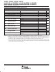
TLC2574/78 DW and PW package devices AC/DC performance
PARAMETER TEST CONDITIONS MIN TYP
†
MAX UNIT
DC Accuracy
E
L
Integral linearity error See Note 6 −1 ±0.5 1 LSB
E
D
Differential linearity error −1 ±0.5 1 LSB
E
O
Bipolar zero error See Note 7 −0.30 ±0.08 0.36 %FS
E
FS(+)
Positive full scale error See Note 7 −0.55 ±0.04 0.61 %FS
E
FS(−)
Negative full scale error See Note 7 −0.30 ±0.13 0.79 %FS
AC Accuracy
SINAD
Signal-to-noise ratio + distortion
f
i
= 20 kHz 70 72
dB
SINAD Signal-to-noise ratio + distortion
f
i
= 100 kHz
70
dB
THD
Total harmonic distortion
f
i
= 20 kHz −82 −76
dB
THD Total harmonic distortion
f
i
= 100 kHz
−80
dB
SNR
Signal-to-noise ratio
f
i
= 20 kHz 71 72
dB
SNR Signal-to-noise ratio
f
i
= 100 kHz
71
dB
ENOB
Effective number of bits
f
i
= 20 kHz 11.3 11.7
Bits
ENOB Effective number of bits
f
i
= 100 kHz
11.3
Bits
SFDR
Spurious free dynamic range
f
i
= 20 kHz 78 83
dB
SFDR Spurious free dynamic range
f
i
= 100 kHz
80
dB
Analog input bandwidth
Full power bandwidth, −3 dB 1 MHz
Analog input bandwidth
Full power bandwidth, −1 dB
700 kHz
Channel-to-channel Isolation
Fixed channel in conversion mode 00, f
i
= 35 kHz,
See Note 8
81 dB
†
All typical values are at T
A
= 25°C.
NOTES: 6. Linear error is the maximum deviation from the best fit straight line through the A/D transfer characteristics.
7. Bipolar zero error is the difference between 100000000000 and the converted output for zero input voltage; positive full-scale error
is the difference between 111111111111 and the converted output for positive full-scale input voltage (10 V); negative full-scale error
is the difference between 000000000000 and the converted output for negative full-scale input voltage (−10 V).
8. It is measured by applying a full-scale of 35 kHz signal to other channels and determining how much the signal is attenuated in the
channel of interest. The converter samples this examined channel continuously. The channel-to-channel isolation is degraded if the
converter samples different channels alternately.