
Datasheet


"#$%
SBOS317D − SEPTEMBER 2004 − REVISED AUGUST 2008
www.ti.com
21
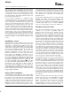
Another type of filter, a high-Q bandpass filter, is shown in
Figure 16. The transfer function for this filter is:
V
OUT
V
IN
+
s
R
3
)R
4
R
1
R
4
C
1
s
2
) s
1
R
1
C
1
)
R
3
R
2
R
4
R
5
C
1
C
2
with w
O
2
+
R
3
R
2
R
4
R
5
C
1
C
2
and
w
O
Q
+
1
R
1
C
1
For the values chosen in Figure 16:
f
O
+
w
O
2p
] 1MHz
and Q = 100
See Figure 17 for the frequency response of the filter
shown in Figure 16.
V
OUT
R
3
500
Ω
R
4
500
Ω
R
5
158
Ω
C
2
1000pF
R
1
15.8k
Ω
R
2
158
Ω
V
IN
C
1
1000pF
1/4
OPA4820
1/4
OPA4820
Figure 16. High-Q 1MHz Bandpass Filter
6
0
−
6
−
12
−
18
−
24
−
30
−
36
−
42
−
48
−
54
−
60
−
66
−
72
Frequency (Hz)
Gain (dB)
100k 1M 10M 100M
Figure 17. High-Q 1MHz Bandpass Filter
Frequency Response
DESIGN-IN TOOLS
DEMONSTRATION FIXTURES
Two printed circuit boards (PCBs) are available to assist
in the initial evaluation of circuit performance using the
OPA4820 in its two package options. Both of these are
offered free of charge as unpopulated PCBs, delivered
with a user’s guide. The summary information for these
fixtures is shown in the table below.
PRODUCT PACKAGE ORDERING NUMBER
LITERATURE
NUMBER
OPA4820ID SO-14 DEM-OPA-SO-4A SBOU016
OPA4820IPW TSSOP-14 DEM-OPA-TSSOP-4A SBOU017
The demonstration fixtures can be requested at the Texas
Instruments web site (www.ti.com) through the OPA4820
product folder.
MACROMODELS AND APPLICATIONS
SUPPORT
Computer simulation of circuit performance using SPICE
is often a quick way to analyze the performance of the
OPA4820 and its circuit designs. This is particularly true for
video and R
F
amplifier circuits where parasitic capaci-
tance and inductance can play a major role on circuit
performance. A SPICE model for the OPA4820 is
available through the TI web page (www.ti.com). The
applications department is also available for design
assistance. These models predict typical small-signal AC,
transient steps, DC performance, and noise under a wide
variety of operating conditions. The models include the
noise terms found in the electrical specifications of the
data sheet. These models do not attempt to distinguish
between the package types in their small-signal AC
performance.
OPERATING SUGGESTIONS
OPTIMIZING RESISTOR VALUES
Since the OPA4820 is a unity-gain stable, voltage-feed-
back op amp, a wide range of resistor values may be used
for the feedback and gain-setting resistors. The primary
limits on these values are set by dynamic range (noise and
distortion) and parasitic capacitance considerations. Usu-
ally, the feedback resistor value should be between 200Ω
and 1kΩ. Below 200Ω, the feedback network will present
additional output loading which can degrade the harmonic
distortion performance of the OPA4820. Above 1kΩ, the
typical parasitic capacitance (approximately 0.2pF)
across the feedback resistor may cause unintentional
band limiting in the amplifier response. A 25Ω feedback
resistor is suggested for A
V
= +1V/V.
A good rule of thumb is to target the parallel combination
of R
F
and R
G
(see Figure 1) to be less than about 200Ω.
The combined impedance R
F
|| R
G
interacts with the
inverting input capacitance, placing an additional pole in
the feedback network, and thus a zero in the forward
(5)
(6)
(7)
(8)