
Datasheet


www.ti.com
SBOS107A
OPA344, 2344, 4344
OPA345, 2345, 4345
11
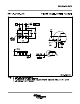
performance curve “Small-Signal Overshoot vs Capacitive
Load.” In unity-gain configurations, capacitive load drive
can be improved by inserting a small (10Ω to 20Ω) resistor,
R
S
, in series with the output, as shown in Figure 5. This
significantly reduces ringing while maintaining dc perfor-
mance for purely capacitive loads. However, if there is a
resistive load in parallel with the capacitive load, a voltage
divider is created, introducing a dc error at the output and
slightly reducing the output swing. The error introduced is
proportional to the ratio R
S
/R
L
, and is generally negligible.
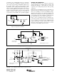
FIGURE 6. OPA344 in Noninverting Configuration Driving ADS7822.
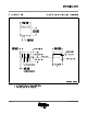
FIGURE 7. Speech Bandpass Filtered Data Acquisition System.
DRIVING A/D CONVERTERS
The OPA344 and OPA345 series op amps are optimized for
driving medium-speed sampling A/D converters. The
OPA344 and OPA345 op amps buffer the A/D’s input
capacitance and resulting charge injection while providing
signal gain.
Figures 6 shows the OPA344 in a basic noninverting con-
figuration driving the ADS7822. The ADS7822 is a 12-bit,
micro-power sampling converter in the MSOP-8 package.
When used with the low-power, miniature packages of the
OPA344, the combination is ideal for space-limited, low-
power applications. In this configuration, an RC network at
the A/D’s input can be used to filter charge injection.
Figure 7 shows the OPA2344 driving an ADS7822 in a
speech bandpass filtered data acquisition system. This small,
low-cost solution provides the necessary amplification and
signal conditioning to interface directly with an electret
microphone. This circuit will operate with V
S
= +2.7V to
+5V with less than 500µA quiescent current.
FIGURE 5. Series Resistor in Unity-Gain Configuration
Improves Capacitive Load Drive.
10Ω to
20Ω
OPA344
V+
V
IN
V
OUT
R
S
R
L
C
L
C
3
33pF
V
+
GND
3
1
8
4
5
6
7
–IN
+IN
2
C
2
DCLOCK
Serial
Interface
1000pF
R
1
1.5kΩ
R
4
20kΩ
R
5
20kΩ
R
6
100kΩ
R
8
150kΩ
R
9
510kΩ
R
7
51kΩ
D
OUT
V
REF
V+
= +2.7V to 5V
CS/SHDN
C
1
1000pF
Electret
Microphone
(1)
G = 100
Passband 300Hz to 3kHz
R
3
1MΩ
R
2
1MΩ
NOTE: (1) Electret microphone
powered by R
1
.
ADS7822
12-Bit A/D
1/2
OPA2344
1/2
OPA2344
ADS7822
12-Bit A/D
DCLOCK
D
OUT
CS/SHDN
OPA344
+5V
V
IN
V+
2
+In
3
–In
V
REF
8
4GND
Serial
Interface
1
0.1µF 0.1µF
7
6
5
NOTE: A/D Input = 0 to V
REF
V
IN
= 0V to 5V for
0V to 5V output.
RC network filters high frequency noise.
500Ω
3300pF