
Datasheet


1
2
3
4
1
0
0.2
0.4
0.6
0.8
1
0
0.2
0.4
0.6
0.8
1
2
3
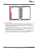
Asynchronous Step Synchronous Step
% V
FSR
Conversion Conversion
SD16_A Operation
www.ti.com
Figure 26-4. Digital Filter Step Response and Conversion Points
26.2.7.1 Digital Filter Output
The number of bits output by the digital filter is dependent on the oversampling ratio and ranges from 15
to 30 bits. Figure 26-5 shows the digital filter output and their relation to SD16MEM0 for each OSR,
LSBACC, and SD16UNI setting. For example, for OSR = 1024, LSBACC = 0, and SD16UNI = 1, the
SD16MEM0 register contains bits 28 - 13 of the digital filter output. When OSR = 32, the one (SD16UNI =
0) or two (SD16UNI=1) LSBs are always zero.
The SD16LSBACC and SD16LSBTOG bits give access to the least significant bits of the digital filter
output. When SD16LSBACC = 1 the 16 least significant bits of the digital filter's output are read from
SD16MEM0 using word instructions. The SD16MEM0 register can also be accessed with byte instructions
returning only the 8 least significant bits of the digital filter output.
When SD16LSBTOG = 1 the SD16LSBACC bit is automatically toggled each time SD16MEM0 is read.
This allows the complete digital filter output result to be read with two reads of SD16MEM0. Setting or
clearing SD16LSBTOG does not change SD16LSBACC until the next SD16MEM0 access.
604
SD16_A SLAU144J–December 2004–Revised July 2013
Submit Documentation Feedback
Copyright © 2004–2013, Texas Instruments Incorporated