
Datasheet


SVS Registers
www.ti.com
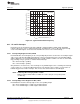
9.3.1 SVSCTL, SVS Control Register
7 6 5 4 3 2 1 0
VLDx PORON SVSON SVSOP SVSFG
rw-0
(1)
rw-0
(1)
rw-0
(1)
rw-0
(1)
rw-0
(1)
r
(1)
r
(1)
rw-0
(1)
VLDx Bits 7-4 Voltage level detect. These bits turn on the SVS and select the nominal SVS threshold voltage level. See
the device-specific data sheet for parameters.
0000 SVS is off
0001 1.9 V
0010 2.1 V
0011 2.2 V
0100 2.3 V
0101 2.4 V
0110 2.5 V
0111 2.65 V
1000 2.8 V
1001 2.9 V
1010 3.05 V
1011 3.2 V
1100 3.35 V
1101 3.5 V
1110 3.7 V
1111 Compares external input voltage SVSIN to 1.25 V.
PORON Bit 3 POR on. This bit enables the SVSFG flag to cause a POR device reset.
0 SVSFG does not cause a POR
1 SVSFG causes a POR
SVSON Bit 2 SVS on. This bit reflects the status of SVS operation. This bit DOES NOT turn on the SVS. The SVS is
turned on by setting VLDx > 0.
0 SVS is Off
1 SVS is On
SVSOP Bit 1 SVS output. This bit reflects the output value of the SVS comparator.
0 SVS comparator output is low
1 SVS comparator output is high
SVSFG Bit 0 SVS flag. This bit indicates a low voltage condition. SVSFG remains set after a low voltage condition until
reset by software.
0 No low voltage condition occurred
1 A low condition is present or has occurred
(1)
Reset by a brownout reset only, not by a POR or PUC.
340
Supply Voltage Supervisor (SVS) SLAU144J–December 2004–Revised July 2013
Submit Documentation Feedback
Copyright © 2004–2013, Texas Instruments Incorporated