
Datasheet


LMV321-N, LMV321-N-Q1, LMV358-N, LMV358-N-Q1
LMV324-N, LMV324-N-Q1
www.ti.com
SNOS012I –AUGUST 2000–REVISED FEBRUARY 2013
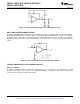
Figure 55. Difference Amplifier
Instrumentation Circuits
The input impedance of the previous difference amplifier is set by the resistors R
1
, R
2
, R
3
, and R
4
. To eliminate
the problems of low input impedance, one way is to use a voltage follower ahead of each input as shown in the
following two instrumentation amplifiers.
Three-Op-Amp Instrumentation Amplifier
The quad LMV324 can be used to build a three-op-amp instrumentation amplifier as shown in Figure 56.
Figure 56. Three-Op-Amp Instrumentation Amplifier
The first stage of this instrumentation amplifier is a differential-input, differential-output amplifier, with two voltage
followers. These two voltage followers assure that the input impedance is over 100 MΩ. The gain of this
instrumentation amplifier is set by the ratio of R
2
/R
1
. R
3
should equal R
1
, and R
4
equal R
2
. Matching of R
3
to R
1
and R
4
to R
2
affects the CMRR. For good CMRR over temperature, low drift resistors should be used. Making R
4
slightly smaller than R
2
and adding a trim pot equal to twice the difference between R
2
and R
4
will allow the
CMRR to be adjusted for optimum performance.
Two-Op-Amp Instrumentation Amplifier
A two-op-amp instrumentation amplifier can also be used to make a high-input-impedance DC differential
amplifier (Figure 57). As in the three-op-amp circuit, this instrumentation amplifier requires precise resistor
matching for good CMRR. R
4
should equal R
1
and, R
3
should equal R
2
.
Copyright © 2000–2013, Texas Instruments Incorporated Submit Documentation Feedback 17
Product Folder Links: LMV321-N LMV321-N-Q1 LMV358-N LMV358-N-Q1 LMV324-N LMV324-N-Q1