
Datasheet


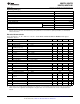


Table Of Contents

1 2 3 4 5 6 7 8 9 10
0
100
200
300
400
500
600
700
SUGGESTED R
F
(:)
GAIN (V/V)
1
10
100
1000
FREQUENCY (MHz)
-8
-7
-6
-5
-4
-3
-2
-1
0
1
GAIN (dB)
R
F
= 400:
R
F
= 600:
R
F
= 147:
R
F
= 300:
A
V
= 2V/V
V
OUT
= 0.5V
PP
LMH6714, LMH6720
LMH6722, LMH6722-Q1
SNOSA39G –NOVEMBER 2002–REVISED APRIL 2013
www.ti.com
APPLICATION SECTION
FEEDBACK RESISTOR SELECTION
One of the key benefits of a current feedback operational amplifier is the ability to maintain optimum frequency
response independent of gain by using appropriate values for the feedback resistor (R
F
). The Electrical
Characteristics and Typical Performance plots specify an R
F
of 300Ω, a gain of +2V/V and ±5V power supplies
(unless otherwise specified). Generally, lowering R
F
from it's recommended value will peak the frequency
response and extend the bandwidth while increasing the value of R
F
will cause the frequency response to roll off
faster. Reducing the value of R
F
too far below it's recommended value will cause overshoot, ringing and,
eventually, oscillation.
Figure 31. Frequency Response vs. R
F
Figure 31 shows the LMH6714/LMH6720/LMH6722's frequency response as R
F
is varied (R
L
= 100Ω, A
V
= +2).
This plot shows that an R
F
of 147Ω results in peaking. An R
F
of 300Ω gives near maximal bandwidth and gain
flatness with good stability. An R
F
of 400Ω gives excellent stability with only a small bandwidth penalty. Since all
applications are slightly different it is worth some experimentation to find the optimal R
F
for a given circuit. Note
that it is not possible to use a current feedback amplifier with the output shorted directly to the inverting input.
The buffer configuration of the LMH6714/LMH6720/LMH6722 requires a 600Ω feedback resistor for stable
operation.
For more information see Application Note OA-13 (SNOA366) which describes the relationship between R
F
and
closed-loop frequency response for current feedback operational amplifiers. The value for the inverting input
impedance for the LMH6714/LMH6720/LMH6722 is approximately 180Ω. The LMH6714/LMH6720/LMH6722 is
designed for optimum performance at gains of +1 to +6 V/V and −1 to −5V/V. When using gains of ±7V/V or
more the low values of R
G
required will make inverting input impedances very low.
When configuring the LMH6714/LMH6720/LMH6722 for gains other than +2V/V, it is usually necessary to adjust
the value of the feedback resistor. Figure 32 and Figure 33 provide recommended feedback resistor values for a
number of gain selections.
Figure 32. R
F
vs. Non-Inverting Gain
10 Submit Documentation Feedback Copyright © 2002–2013, Texas Instruments Incorporated
Product Folder Links: LMH6714 LMH6720 LMH6722 LMH6722-Q1