
Datasheet


LM77
www.ti.com
SNIS103F –JUNE 1999–REVISED MARCH 2013
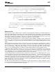
Figure 13. Typical Pointer Set Followed by Immediate Read from Configuration Register
Figure 14. Configuration Register Write
Comparison Register Write
Figure 15. Timing Diagrams
Application Hints
The temperature response graph in Figure 16 depicts a typical application designed to meet ACPI requirements.
In this type of application, the temperature scale is given an arbitrary value of "granularity", or the window within
which temperature notification events should occur. The LM77 can be programmed to the window size chosen by
the designer, and will issue interrupts to the processor whenever the window limits have been crossed. The
internal flags permit quick determination of whether the temperature is rising or falling.
The T_CRIT limit would typically use its separate output to activate hardware shutdown circuitry separate from
the processor. This is done because it is expected that if temperature has gotten this high that the processor may
not be responding. The separate circuitry can then shut down the system, usually by shutting down the power
supply.
Note that the INT and T_CRIT_A outputs are separate, but can be wire-or'd together. Alternatively the T_CRIT_A
can be diode or'd to the INT line in such a way that a T_CRIT_A event activates the INT line, but an INT event
does not activate the T_CRIT_A line. This may be useful in the event that it is desirable to notify both the
processor and separate T_CRIT_A shutdown circuitry of a critical temperature alarm at the same time (maybe
the processor is still working and can coordinate a graceful shutdown with the separate shutdown circuit).
To implement ACPI compatible sensing it is necessary to sense whenever the temperature goes outside the
window, issue an interrupt, service the interrupt, and reprogram the window according to the desired granularity
of the temperature scale. The reprogrammed window will now have the current temperature inside it, ready to
issue an interrupt whenever the temperature deviates from the current window.
To understand this graph, assume that at the left hand side the system is at some nominal temperature. For the
1st event temperature rises above the upper window limit, T
HIGH
, causing INT to go active. The system responds
to the interrupt by querying the LM77's status bits and determines that T
HIGH
was exceeded, indicating that
temperature is rising. The system then reprograms the temperature limits to a value higher by an amount equal
to the desired granularity. Note that in Event Interrupt Mode, reprogramming the limits has caused a second,
known, interrupt to be issued since temperature has been returned within the window. In Comparator Interrupt
Mode, the LM77 simply stops issuing interrupts.
The 2nd event is another identical rise in temperature. The 3rd event is typical of a drop in temperature. This is
one of the conditions that demonstrates the power of the LM77, as the user receives notification that a lower limit
is exceeded in such a way that temperature is dropping.
Copyright © 1999–2013, Texas Instruments Incorporated Submit Documentation Feedback 13
Product Folder Links: LM77