
Datasheet


UVLO
SW Pin
Inductor
Current
Vin
t2
I
LIM
V
CC
V
IN
t1
t3
I
O
0V
V
OUT
LM5006
SNVS646B –FEBRUARY 2011–REVISED MARCH 2013
www.ti.com
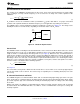
C3 must be located as close as possible to the VCC and RTN pins. In applications with a relatively high input
voltage, power dissipation in the bias regulator is a concern. An auxiliary voltage of between 7.5V and 10V can
be diode connected to the VCC pin to shut off the V
CC
regulator, thereby reducing internal power dissipation. The
current required into the VCC pin depends on the voltage applied to VCC, the switching frequency, and whether
a flyback diode (D1) or a synchronous rectifier (Q1) is used. See Figure 6. Internally a diode connects VCC to
VIN requiring that the auxiliary voltage be less than V
IN
.
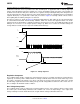
The turn-on sequence is shown in Figure 33. During the initial delay (t1) VCC ramps up at a rate determined by
its current limit and C3 while internal circuitry stabilizes. When V
CC
reaches the upper threshold of its under-
voltage lock-out, the buckswitch is enabled. The inductor current increases to the current limit threshold (I
LIM
) and
during t2 V
OUT
increases as the output capacitor charges up. When V
OUT
reaches the intended voltage the
average inductor current decreases (t3) to the nominal load current (I
O
).
Figure 33. Startup Sequence
Regulation Comparator
The feedback voltage at FB is compared to an internal 2.5V reference. In normal operation (the output voltage is
regulated), an on-time period is initiated when the voltage at FB falls below 2.5V. The buck switch stays on for
the on-time, causing the FB voltage to rise above 2.5V. After the on-time period, the buck switch stays off until
the FB voltage again falls below 2.5V. During start-up, the FB voltage will be below 2.5V at the end of each on-
time, resulting in the minimum off-time of 260 ns.
Over-Voltage Comparator
The feedback voltage at FB is compared to an internal 2.85V reference. If the voltage at FB rises above 2.85V
the on-time pulse is immediately terminated. This condition can occur if the input voltage, or the output load,
change suddenly. The buck switch will not turn on again until the voltage at FB falls below 2.5V.
12 Submit Documentation Feedback Copyright © 2011–2013, Texas Instruments Incorporated
Product Folder Links: LM5006