
Datasheet


L =
V
IN
2 x 'i
L
x DT
S
¨
©
§
¸
¹
·
¸
¸
¹
·
¨
¨
©
§
=
2L
IN
V
L
Âi
x
S
DT
¨
¨
©
§
=
L
V
IN
'i2 L
DT
S
¸
¸
¹
·
L
t
L
i
L
i'
S
T
S
DT
( )
tL
I
L
V
IN
VV
OUT
IN
-
K
=
c
D
V
OUT
V
IN
D =
V
OUT
-
IN
V
OUT
V
LM2735
www.ti.com
SNVS485F –JUNE 2007–REVISED APRIL 2013
Therefore:
(2)
Power losses due to the diode (D1) forward voltage drop, the voltage drop across the internal NMOS switch, the
voltage drop across the inductor resistance (R
DCR
) and switching losses must be included to calculate a more
accurate duty cycle (See Calculating Efficiency, and Junction Temperature for a detailed explanation). A more
accurate formula for calculating the conversion ratio is:
where
• Where η equals the efficiency of the LM2735 application. (3)
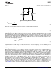
The inductor value determines the input ripple current. Lower inductor values decrease the size of the inductor,
but increase the input ripple current. An increase in the inductor value will decrease the input ripple current.
Figure 21. Inductor Current
(4)
A good design practice is to design the inductor to produce 10% to 30% ripple of maximum load. From the
previous equations, the inductor value is then obtained.
where
• 1/T
S
= F
SW
= switching frequency (5)
One must also ensure that the minimum current limit (2.1A) is not exceeded, so the peak current in the inductor
must be calculated. The peak current (I
LPK
) in the inductor is calculated by:
IL
pk
= I
IN
+ ΔI
L
(6)
or
IL
pk
= I
OUT
/ D' + ΔI
L
(7)
When selecting an inductor, make sure that it is capable of supporting the peak input current without saturating.
Inductor saturation will result in a sudden reduction in inductance and prevent the regulator from operating
correctly. Because of the speed of the internal current limit, the peak current of the inductor need only be
specified for the required maximum input current. For example, if the designed maximum input current is 1.5A
and the peak current is 1.75A, then the inductor should be specified with a saturation current limit of >1.75A.
There is no need to specify the saturation or peak current of the inductor at the 3A typical switch current limit.
Copyright © 2007–2013, Texas Instruments Incorporated Submit Documentation Feedback 11
Product Folder Links: LM2735