
Datasheet


LM2599
SNVS123C –APRIL 1998–REVISED APRIL 2013
www.ti.com
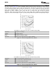
The curves shown in Figure 39 show the LM2599S (TO-263 package) junction temperature rise above ambient
temperature with a 2A load for various input and output voltages. This data was taken with the circuit operating
as a buck switching regulator with all components mounted on a pc board to simulate the junction temperature
under actual operating conditions. This curve can be used for a quick check for the approximate junction
temperature for various conditions, but be aware that there are many factors that can affect the junction
temperature. When load currents higher than 2A are used, double sided or multilayer pc-boards with large
copper areas and/or airflow might be needed, especially for high ambient temperatures and high output voltages.
Circuit Data for Temperature Rise Curve TO-220 Package (NDZ)
Capacitors Through hole electrolytic
Inductor Through hole Renco
Diode Through hole, 5A 40V, Schottky
PC board 3 square inches single sided 2 oz. copper (0.0028″)
Figure 38. Junction Temperature Rise, TO-220
Circuit Data for Temperature Rise Curve TO-263 Package (KTW)
Capacitors Surface mount tantalum, molded “D” size
Inductor Surface mount, Pulse engineering, 68 μH
Diode Surface mount, 5A 40V, Schottky
PC board 9 square inches single sided 2 oz. copper (0.0028″)
Figure 39. Junction Temperature Rise, TO-263
30 Submit Documentation Feedback Copyright © 1998–2013, Texas Instruments Incorporated
Product Folder Links: LM2599