
Datasheet


INA217
7
SBOS247B
www.ti.com
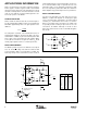
FIGURE 3. Offset Voltage Adjustment Circuit.
OFFSET VOLTAGE TRIM
A variable voltage applied to pin 5, as shown in Figure 3, can
be used to adjust the output offset voltage. A voltage applied
to pin 5 is summed with the output signal. An op amp
connected as a buffer is used to provide a low impedance at
pin 5 to assure good common-mode rejection.
INA217
V+
V–
V
O
V+
150Ω
10kΩ
150Ω
100µA
100µA
2
1
8
R
G
3
5
7
4
6
V–
OPA237
MICROPHONE AMPLIFIER
Figure 4 shows a typical circuit for a professional microphone
input amplifier. R
1
and R
2
provide a current path for conven-
tional 48V phantom power source for a remotely located
microphone. An optional switch allows phantom power to be
disabled. C
1
and C
2
block the phantom power voltage from
the INA217 input circuitry. Non-polarized capacitors should
be used for C
1
and C
2
if phantom power is to be disabled. For
additional input protection against ESD and hot-plugging,
four IN4148 diodes may be connected from the input to
supply lines.
R
4
and R
5
provide a path for input bias current of the INA217.
Input offset current (typically 100nA) creates a DC differential
input voltage that will produce an output offset voltage. This
is generally the dominant source of output offset voltage in
this application. With a maximum gain of 1000 (60dB), the
output offset voltage can be several volts. This may be
entirely acceptable if the output is AC-coupled into the
subsequent stage. An alternate technique is shown in Figure 4.
An inexpensive FET-input op amp in a feedback loop drives
the DC output voltage to 0V. A2 is not in the audio signal path
and does not affect signal quality.
Gain is set with a variable resistor, R
7
, in series with R
6
.
R
6
determines the maximum gain. The total resistance,
R
6
+ R
7
, determines the lowest gain. A special reverse-log
taper potentiometer for R
7
can be used to create a linear
change (in dB) with rotation.
R
5
2.2kΩ
R
6
(2)
8Ω
R
7
(3)
1.6kΩ
A1
INA217
+
47µF
R
3
47kΩ
R
2
6.8kΩ
R
1
6.8kΩ
Phantom Power
+48V
+
+
R
4
2.2kΩ
C
1
(1)
47µF
60V
C
2
(1)
47µF
60V
A2
OPA137
0.1µF
+15V
0.1µF
0.1µF
1MΩ
V
O
–15V
Optional DC
output control loop.
6
7
5
4
1
2
3
Female XLR
Connector
NOTES: (1) Use non-polar capacitors if phantom power is to be
turned off. (2) R
6
sets maximum gain. (3) R
7
sets minimum gain.
(4) Optional IN4148 prevents damage due to ESD and hot-plugging.
+15V
–15V
IN4148
(4)
+15V
–15V
IN4148
(4)
FIGURE 4. Phantom-Powered Microphone Preamplifier.