
Datasheet


old and power is lost at V
CC
, the SuperCap on VBATT
discharges through V
CC
until VBATT reaches the reset
threshold; then the battery-backup mode is initiated and
the current through V
CC
goes to zero.
Using Separate Power Supplies
for VBATT and V
CC
If using separate power supplies for V
CC
and VBATT,
VBATT must be less than 0.3V above V
CC
when V
CC
is
above the reset threshold. As described in the previous
section, if VBATT exceeds this limit and power is lost at
V
CC
, current flows continuously from VBATT to V
CC
via
the VBATT-to-V
OUT
diode and the V
OUT
-to-V
CC
switch
until the circuit is broken (Figure 8).
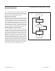
Alternate Chip-Enable Gating
Using memory devices with both CE and CE inputs allows
the CE loop to be bypassed. To do this, connect CE IN to
ground, pull up CE OUT to V
OUT
, and connect CE OUT to
the CE input of each memory device (Figure 10). The CE
input of each part then connects directly to the chip-select
logic, which does not have to be gated.
Figure10. Alternate CE Gating Figure 11. Adding Hysteresis to the Power-Fail Comparator
Figure 12. Monitoring a Negative Voltage
MAX691A
MAX693A
MAX800L
MAX800M
V
OUT
GND
CE IN
CE
CE
CE OUT
CE
CE
CE
CE
CE
CE
*MAXIMUM Rp VALUE DEPENDS ON
THE NUMBER OF RAMS.
MINIMUM Rp VALUE IS 1kΩ.
ACTIVE-HIGH
CE LINES
FROM LOGIC
RAM 1
RAM 2
RAM 3
RAM 4
Rp*
MAX691A
MAX693A
MAX800L
MAX800M
V
CC
GND
PFI
*OPTIONAL
R2
R3
R1
V
IN
+5V
C1*
TO µP
PFO
V
TRIP
= 1.25
R1 + R2
R2
V
H
= 1.25/
R2 I I R3 V
L
- 1.25
+
5 - 1.25
=
1.25
R1 + R2 I I R3 R1 R3 R2
PFO
5V
0V
0V V
H
V
TRIP
V
IN
V
L
MAX691A
MAX693A
MAX800L
MAX800M
V
CC
GND
PFI
R2
R1
+5V
PFO
PFO
5V
0V
NOTE: V
TRIP
IS NEGATIVE.
0V
V
TRIP
V-
5 - 1.25
=
1.25 - V
TRIP
R1 R2
V-
MAX691A/MAX693A/
MAX800L/MAX800M
Microprocessor Supervisory Circuits
www.maximintegrated.com
Maxim Integrated
│
13