
Datasheet


Applications Information
Thermal Considerations
The MAX6509/MAX6510 supply current is typically
32µA. When used to drive high-impedance loads, the
devices dissipate negligible power; therefore, the die
temperature is essentially the same as the package
temperature. The key to accurate temperature monitor-
ing is good thermal contact between the MAX6509/
MAX6510 package and the device being monitored. In
some applications, the SOT23-5 and SOT23-6 pack-
ages may be small enough to fit underneath a socketed
?P, allowing the device to monitor the µP’s temperature
directly. Use the monitor’s output to reset the µP, assert
an interrupt, or trigger an external alarm. Accurate tem-
perature monitoring depends on the thermal resistance
between the device being monitored and the MAX6509/
MAX6510 die.
The rise in die temperature due to self-heating is given by
the following formula:
∆T
J
= P
DISS
· θ JA
where PDISS is the power dissipated by the MAX6509/
MAX6510, and qJA is the package’s thermal resistance.
The typical thermal resistance is 115°C/W for the SOT23-
6 package. To limit the effects of self-heating, minimize
the output currents. For example, if the MAX6510 sinks
5mA, the output voltage is guaranteed to be less than
0.3V; therefore, an additional 1.5mW of power is dissi-
pated within the IC. This corresponds to a 0.173°C shift in
the die temperature in the SOT23-6.
Temperature-Window Detector
The MAX6509/MAX6510 temperature switch outputs
assert when the die temperature is outside the pro-
grammed range. Combining the outputs of a set-cold
and a set-hot device creates an over/undertemperature
detector. The MAX6509/MAX6510 are designed to form
two complementary pairs, each containing one cold trip
point output and one hot trip point output. The assertion
of either output alerts the system to an out-of-range tem-
perature. The MAX6510 push-pull output stages can be
ORed to produce a thermal out-of-range alarm. More
favorably, a MAX6509HAUK+T and MAX6509CAUK+T
can be directly wire-ORed with a single external resistor
to accomplish the same task (Figure 5).
The temperature window (alarms or detectors as in
Figure 5) can be used to accurately determine when a
device’s temperature falls out of a programmed range,
for example -3°C to +75°C as shown in Figure 5. The
thermal overrange signal can be used to assert a ther-
mal shutdown, power-up, recalibration, or other tem-
perature-dependent function.
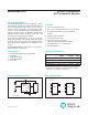
Figure 4. Temperature Response
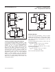
Figure 3. Overtemperature Fan ControlFigure 2. Microprocessor Alarm/Reset
THYST = 2°C
SET HOT
OUT
OUT
TEMPERATURE
MAX6509H
MAX6510C
OUTSET = GND
SET COLD
98°C100°C
T
THRESHOLD
= -10°C
T THRESHOLD = 65°C100°C
98°C
-38°C
-40°C
-38°C-40°C
MAX6510
+5V
OUTGND
V
CC
R
SET
OUTSET SET
HYST
µP FAN
HEAT
V
CC
MAX6509
+3.3V
GND
SET
HYST
V
CC
µP
HEAT
V
CC
R
PULL-UP
100k
R
SET
OUT
INT
SHUTDOWN
OR
RESET
MAX6509/MAX6510 Resistor-Programmable
SOT Temperature Switches
www.maximintegrated.com
Maxim Integrated
│
6