
Datasheet


MAX6301–MAX6304
+5V, Low-Power µP Supervisory Circuits
with Adjustable Reset/Watchdog
_______________________________________________________________________________________ 5
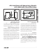
Pin Description
PIN NAME FUNCTION
1 RESET IN
Reset Input. High-impedance input to the reset comparator. Connect this pin to the center point of an
external resistor voltage-divider network to set the reset threshold voltage. The reset threshold voltage is
calculated as follows: V
RST
= 1.22 x (R1 + R2)/R2 (see the Typical Operating Circuit).
2 GND Ground
3 SRT
Set Reset-Timeout Input. Connect a capacitor between this input and ground to select the reset timeout
period (t
RP
). Determine the period as follows: t
RP
= 2.67 x C
SRT
, with C
SRT
in pF and t
RP
in µs (see the
Typical Operating Circuit).
4SWT
Set Watchdog-Timeout Input. Connect a capacitor between this input and ground to select the basic
watchdog timeout period (t
WD
). Determine the period as follows: t
WD
= 2.67 x C
SWT
, with C
SWT
in pF and
t
WD
in µs. The watchdog function can be disabled by connecting this pin to ground.
5 WDS
Watchdog-Select Input. This input selects the watchdog mode. Connect to ground to select normal mode
and the basic watchdog timeout period. Connect to V
CC
to select extended mode, multiplying the basic
timeout period by a factor of 500. A change in the state of this pin resets the watchdog timer to zero.
6 WDI
Watchdog Input. A rising or falling transition must occur on this input within the selected watchdog timeout
period, or a reset pulse will occur. The capacitor value selected for SWT and the state of WDS determine
the watchdog timeout period. The watchdog timer clears and restarts when a transition occurs on WDI or
WDS. The watchdog timer is cleared when reset is asserted and restarted after reset deasserts. In the
extended watchdog mode (WDS = V
CC
), the watchdog function can be disabled by driving WDI with a
three-stated driver or by leaving WDI unconnected.
Open-Drain, Active-Low Reset
Output (MAX6301)
RESET
(MAX6301/
MAX6303)
Push-Pull, Active-Low Reset
Output (MAX6303)
RESET changes from high to low whenever the monitored voltage (V
IN
)
drops below the selected reset threshold (V
RST
). RESET remains low as
long as V
IN
is below V
RST
. Once V
IN
exceeds V
RST
, RESET remains low
for the reset timeout period and then goes high. The watchdog timer
triggers a reset pulse (t
RP
) whenever the watchdog timeout period (t
WD
)
is exceeded.
Open-Drain, Active-High Reset
Output (MAX6302)
7
RESET
(MAX6302/
MAX6304
Push-Pull, Active-High Reset
Output (MAX6304)
RESET changes from low to high whenever the monitored voltage (V
IN
)
drops below the selected reset threshold (V
RST
). RESET remains high as
long as V
IN
is below V
RST
. Once V
IN
exceeds V
RST
, RESET remains high
for the reset timeout period and then goes low. The watchdog timer
triggers a reset pulse (t
RP
) whenever the watchdog timeout period (t
WD
)
is exceeded.
8V
CC
Supply Voltage. Bypass to ground with a 0.1µF capacitor placed as close as possible to the pin.