
Datasheet


__________Applications Information
Unipolar Output
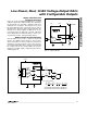
Figure 9 depicts the MAX5152/MAX5153 configured for
unity-gain, unipolar operation. Table 2 lists the unipolar
output codes. To increase dynamic range, specific
gain configurations can be used as shown in Figure 10.
Bipolar Output
The MAX5152/MAX5153 can be configured for a bipo-
lar output, as shown in Figure 11. The output voltage is
given by the equation:
V
OUT
= V
REF
[((2 x NB) / 8192) - 1]
where NB represents the numeric value of the DAC’s
binary input code. Table 3 shows digital codes and the
corresponding output voltage for Figure 11’s circuit.
MAX5152/MAX5153
Low-Power, Dual, 13-Bit Voltage-Output DACs
with Configurable Outputs
______________________________________________________________________________________ 13
TO OTHER
SERIAL DEVICES
MAX5152
MAX5153
DIN
SCLK
CS
MAX5152
MAX5153
DIN
SCLK
CS
MAX5152
MAX5153
DIN
SCLK
CS
DIN
SCLK
CS1
CS2
CS3
Figure 8. Multiple MAX5152/MAX5153s Sharing a Common DIN Line
MAX5152
MAX5153
DAC
REF_
OUT_
FB_
DGND
AGND
+5V/+3V
V
DD
Figure 9. Unipolar Output Circuit
Table 2. Unipolar Code Table (Gain = +1)
00000 0000 0001
0V00000 0000 0000
01111 1111 1111
10000 0000 0000
DAC CONTENTS
MSB LSB
10000 0000 0001
11111 1111 1111
ANALOG OUTPUT
+V
8191
8192
REF
+V
4097
8192
REF
+V
4095
8192
REF
+V
1
8192
REF
+V
4096
8192
V
2
REF
REF
=