
ICC ESR-2197 for Steel Deck and Concrete-Filled Deck Diaphragm Attachment


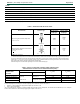


Table Of Contents

ESR-2197
|
Most Widely Accepted and Trusted Page 6 of 23
TABLE 3—ALLOWABLE DIAPHRAGM SHEARS, S
nf
/Ω
nf
(plf) AND FLEXIBILITY FACTORS, F (micro-inches/lb)
1,2
(F = 1000/G') where the diaphragm stiffness (G') is in kips/in
DECK: 1
1
/
2
-INCH DEEP, 6-INCH ON CENTER FLUTES (see figures below)
FRAME FASTENERS: HILTI X-HSN 24 (see applicable patterns below)
SIDELAP CONNECTIONS: MINIMUM No. 10 SELF-DRILLING SCREW (see Section 3.7)
PATTERN 36/9
PATTERN 36/11
For SI: 1 inch = 25.4 mm, 1 foot = 305 mm, 1 plf = 14.6 N/m, 1 psi = 6.89 kPa, 1inch/lb = 5.7 mm/N.
1
Refer to footnotes following Table 18 for additional installation and design requirements.
2
Allowable stress design diaphragm capacities are presented for diaphragms mechanically connected to the structure
subjected to earthquake loads or load combinations which include earthquake loads. Diaphragm shears may be increased
for other applications as prescribed in Section 4.1 of this report.
GAGE
SIDELAP
CONNECTION
FACTOR
SPAN (FT–IN.)
4′-0″ 5′-0″ 6′-0″ 7′-0″ 8′-0″ 9′-0″ 10′-0″
FASTENERS PER SHEET TO SUPPORT
9 11 9 11 9 11 9 11 9 11 9 11 9 11
22
Screws
@ 12″ o.c.
S
nf
/Ω
nf
659 762 576 658 516 582 465 520 426 474 398 440 376 415
F 15.6 15.3 14.1 13.9 13.2 12.9 12.6 12.3 12.2 11.9 11.8 11.5 11.6 11.3
Screws
@ 8″ o.c.
S
nf
/Ω
nf
723 831 645 732 589 662 547 610 515 565 489 531 467 505
F 15.1 14.9 13.6 13.4 12.5 12.3 11.8 11.6 11.3 11.1 10.9 10.7 10.6 10.4
Screws
@ 6″ o.c.
S
nf
/Ω
nf
782 896 710 802 658 735 619 686 588 647 564 617 544 592
F 14.8 14.6 13.1 13.0 12.1 11.9 11.3 11.2 10.8 10.6 10.3 10.2 10.0 9.9
20
Screws
@ 12″ o.c.
S
nf
/Ω
nf
812 937 713 813 642 725 588 654 541 598 504 555 477 524
F 11.2 11.0 10.4 10.2 9.9 9.7 9.6 9.4 9.4 9.1 9.2 9.0 9.1 8.9
Screws
@ 8″ o.c.
S
nf
/Ω
nf
896 1028 804 910 738 827 689 765 650 718 620 676 595 645
F 10.8 10.6 9.9 9.7 9.3 9.1 8.9 8.7 8.6 8.5 8.4 8.2 8.2 8.1
Screws
@ 6″ o.c.
S
nf
/Ω
nf
972 1113 888 1003 827 924 781 865 746 820 718 784 694 755
F 10.5 10.4 9.5 9.4 8.9 8.8 8.5 8.3 8.1 8.0 7.9 7.8 7.7 7.6
18
Screws
@ 12″ o.c.
S
nf
/Ω
nf
1099 1266 973 1106 882 993 814 910 762 841 717 784 678 739
F 7.3 7.1 7.0 6.8 6.9 6.7 6.8 6.6 6.8 6.5 6.7 6.5 6.7 6.5
Screws
@ 8″ o.c.
S
nf
/Ω
nf
1222 1401 1107 1251 1024 1145 962 1067 914 1006 875 958 844 918
F 6.9 6.8 6.6 6.4 6.3 6.2 6.2 6.0 6.1 5.9 6.0 5.9 5.9 5.8
Screws
@ 6″ o.c.
S
nf
/Ω
nf
1333 1526 1229 1387 1154 1288 1097 1214 1053 1157 1018 1112 989 1075
F 6.7 6.6 6.3 6.2 6.0 5.9 5.8 5.7 5.7 5.6 5.6 5.5 5.5 5.4