
Data Sheet


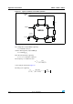
Table Of Contents
- 1 Schematic diagrams
- 2 Absolute maximum ratings and operating conditions
- 3 Electrical characteristics
- Table 3. Tamb = +25˚ C, VCC = +5 V to +15 V (unless otherwise specified)
- Figure 3. Minimum pulse width required for triggering
- Figure 4. Supply current versus supply voltage
- Figure 5. Delay time versus temperature
- Figure 6. Low output voltage versus output sink current
- Figure 7. Low output voltage versus output sink current
- Figure 8. Low output voltage versus output sink current
- Figure 9. High output voltage drop versus output
- Figure 10. Delay time versus supply voltage
- Figure 11. Propagation delay versus voltage level of trigger value
- 4 Application information
- 5 Package information
- 6 Ordering information
- 7 Revision history

NE555 - SA555 - SE555 Application information
Doc ID 2182 Rev 6 9/20
Figure 13. Waveforms in monostable operation
Figure 14. Pulse duration versus R1C1
4.2 Astable operation
When the circuit is connected as shown in Figure 15 (pins 2 and 6 connected) it triggers
itself and free runs as a multi-vibrator. The external capacitor charges through R
1
and R
2
and discharges through R
2
only. Thus the duty cycle can be set accurately by adjusting the
ratio of these two resistors.
In the astable mode of operation, C
1
charges and discharges between 1/3 V
CC
and 2/3 V
CC
.
As in the triggered mode, the charge and discharge times and, therefore, frequency are
independent of the supply voltage.
CAPACITOR VOLTAGE = 2.0V/div
t = 0.1 ms / div
INPUT = 2.0V/div
OUTPUT VOLTAGE = 5.0V/div
R1 = 9.1kΩ, C1 = 0.01μF, R = 1kΩ
L
C
(μF)
10
1.0
0.1
0.01
0.001
10 100 1.0 10 100 10 (t )
d
μs μs
ms ms mss
10
M
Ω
1M
Ω
1
00
k
Ω
10k
Ω
R1
=
1k
Ω