
User's Manual


This document is not allowed to
transmit without ZTE Corporation’s
permission. ©ZTE CORPORATION All rights reserved
第 17 页
Regarding the return loss, the Module provides the following values in the active band:
Table 6-1 Return Loss in the Active Band
State of Module
Return Loss of
Module
Recommended Return Loss of
Application
Receive ≥ 8dB ≥ 12dB
Transmit not applicable ≥ 12dB
The connection of the antenna or other equipment must be de coupled from DC voltage. This is necessary
because the antenna connector is DC coupled to ground via an inductor for ESD protection.
6.1 Antenna Installation
To suit the physical design of individual applications, the MC2261 offers two alternative approached to
connecting the antenna:
■ Recommended approach:
MM9329-2700B antenna connector manufactured by MURATA assembled on
the component side of the PCB (top view on Module). See Section 4.3 for details.
■ Antenna pad and grounding plane placed on the bottom side. See Section 4.2 for details.
The
MM9329-2700B connector has been chosen as antenna reference point (ARP) for the ZTEMT
reference equipment submitted to type approve the MG2639 Module. All RF data specified throughout this
manual are related to the ARP. For compliance with the test results of the ZTEMT type approval you are
advised to give priority to the connector, rather than using the antenna pad.
Note: Both solutions can be applied alternatively. This means,if the antenna is connected to the pad, then
the connector on the Module must be left empty,and when the antenna is connected to the Module
connector, the pad is useless,
6.2 Antenna Pad
The antenna pad of the module is soldered to the board on the customer design to connect with RF line.
For proper grounding connect the RF line to the ground plane on the bottom of the MG2639 Module which
must be connected to the ground plane of the application.
Consider that according to GSM recommendations as 50Ω connector is mandatory for type approval
measurements. It must be ensured that the RF line which is connected to antenna pad should be controlled
on 50Ω.
Notes on soldering
■ To prevent damage to the Module and to obtain long-term solder joint properties, you are advised to
maintain the standards of good engineering practice for soldering.
Material Properties
■ MG2639 Module PCB: FR4
■ Antenna pad: Gold plated pad
6.3 Antenna connector
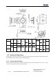
The MG2639 Module uses a microwave coaxial connector supplied by Murata Ltd. The product name is
MM9329-2700B. The position of the antenna connector on the Module PCB can be seen in Figure 6-3.
Figure 6-3 Specification of
MM9329-2700B connector