
User's Manual


User Manual
This document is not allowed to
transmit without ZTE Corporation’s
permission
©ZTE CORPORATION All rights reserved
13
I2C
53
SDA
I/O
I2C data
cable
2.8V IO
54
SCL
Output
I2C clock
cable
2.8V IO
Note: the software doesn’t support this interface by default, therefore it requires
customization.
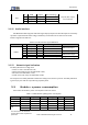
3.1.4 SPI
ZTE MG2639 module provides one SPI BUS interface, SPICS & SPISCK signal multiplex with the
I2C interface, while SPIMOSI & SPIMISO signals multiplex with the UART interface. When UART2 and
I2C function are not used, it can be configured as the SPI interface.
Table 3-3 SPI Interface signal definitions
Classification
No.
Definitions
I/O
Description
Remarks
SPI
53
SPICS
Output
SPI chip select
2.8V IO
54
SPISCK
Output
SPI clock
2.8V IO
29
SPIMOSI
Input
SPI data input
2.8V IO
30
SPIMISO
Output
SPI data output
2.8V IO
Note: the software doesn’t support this interface by default, therefore it requires
customization.
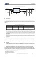
3.1.5 PCM
ZTE MG2639 module adopts its 56-60 PINs as the PCM interface, through which users can
expand the audio DAC.
Table 3-4 PCM interface signal definitions
Classification
No.
Definitions
I/O
Description
Remarks
PCM
56
PCMRST
Output
Reset external PCM
settings
2.8V IO
57
PCMOUT
Output
PCM data output
2.8V IO
58
PCMCLK
Output
PCM clock
2.8V IO
59
PCMSYNC
Output
PCM bytes SYNC
2.8V IO
60
PCMIN
Input
PCM data input
2.8V IO
Note: the software doesn’t support this interface by default, therefore it requires
customization.