
User's Manual


ZXC10-BTS (V5.4) Installation Manual
7-32
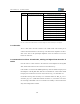
Serial No. End A Outgoing Direction Flag End B Outgoing Direction Flag
B4:BTS set top-BSC(EXT)_T1_1(OUT1)
B5:BTS set top- BSC(EXT)_T1_2(IN2)
B6:BTS set top- BSC(EXT)_T1_2(OUT2)
B7:BTS set top- BSC(EXT)_T1_3(IN3)
B8:BTS set top- BSC(EXT)_T1_3(OUT3)
B9:BTS set top- BSC(EXT)_T1_4(IN4)
B10:BTS set top- BSC(EXT)_T1_4(OUT4)
B11:BTS set top- BSC(EXT)_T1_4(IN5)
B12:BTS set top- BSC(EXT)_T1_5(OUT5)
B13:BTS set top- BSC(EXT)_T1_6(IN6)
B14:BTS set top- BSC(EXT)_T1_6(OUT6)
B15:BTS set top- BSC(EXT)_T1_7(IN7)
(EXT_T1)
B16:BTS set top- BSC(EXT)_T1_7(OUT7)
Note: The T1 cable at the extended interface is selected according to the contract. Normally it is not configured.
7.4.3 Function
The T1 cable used at the Abis interface is the 100Ω coaxial cable twisted pair. It
connects the board interfaces to the rack top. The characteristic impedance of the T1
cable is the same as the input/output impedance of the line transceiver set for the
board’s T1 transceiver.
7.4.4 Connection Positions of Both Ends, Cabling and Signal Flow Direction of
Cables
One end of the T1 cable connects to the connector on the backplane of the IP_BDS
shelf, and the other connects to the conversion card at the rack top.
If the 100Ω T1 is used, then the DB44 high-density connector should be employed on
the backplane of the IP_BDS shelf, while the CC4 standard T1 coaxial socket should
be employed to connect the conversion card, as shown in Fig. 7.4-1 and Table 7.4-1.
On the BTS rack top, there are totally 16 T1 interfaces marked as “BSC_IP_T1-0-7”
and “EXT_IP_T1-0-7” (100Ω cable terminals are shown in ). 8 out of the 16 are active
for connecting with the BSC. The rest T1 interfaces are standby or will be used for the
daisy chain configuration of a BTS.