
User's Manual


ZXC10 BTSB (V1.0) cdma2000 Base Transceiver Station Installation Manual
9-2
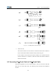
End A End B1 End B2 End B3
Cable code/A
OUT_MON
Cable code/B1 ~ B10
SW_IN
Cable code/B11 ~ B15
CTRL_OUT
Cable code/B16
HUM. TEMP_MON
End B4 End B5 End B6
Cable code/B17
DOOR_MON
Cable code/B18
INFRARED_MON
Cable code/B19
SMOG_MON
End A is connected to the socket OUT_MON on the BIM4 interface board of the BDS
cabinet (if there is no BDS, it is connected to the OUT_MON D_SUB44 socket on the
top of RFS cabinet). B1 to B3 and B5 to B6 are transferred to the installation board of
the feeder rack. End B1 provides input for 10 pairs of switches, End B2 outputs 5 pairs
of control variables, End B3 connects with the cables of temperature and humidity
sensor, End B4 connects with the access control sensor of the equipment room, B5
connects with the infrared sensor cable and B6 connects with the smog sensor cable.
The installation of the temperature/humidity sensor and the smog sensor are the same
as that of the IS95/1X system.
9.2 Installing the Monitoring System
9.2.1 Installing the Indoor Smog Sensor
The smog sensor should be installed on the ceiling as close to the rack as possible. The
installation steps are as follows:
1. As shown in b) of Fig. 9.2-1, separate the upper part and the lower part of the
smog sensor.
2. Connect the green and red cables (as shown in a) of Fig. 9.2-1) at End B of the
10 m smog sensor cable to the two terminals marked 1 and 3 at the bottom of the
smog sensor (as shown in c) of Fig. 9.2-1).
3. Reassemble the upper and lower parts together, as shown in b) of Fig. 9.2-1.
4. Connect the DB25 plug at End A to the End B6 of the external monitoring cable
of RFS.
The terminal connection of the smog sensor cable connector is described in Fig. 9.2-1.