
User's Manual


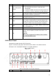


Table Of Contents
- Regulatory Information
- Cybersecurity Recommendations
- Foreword
- Important Safeguards and Warnings
- 1 Product Introduction
- 2 Dimension and Installation
- 3 Boot up the Device
- 4 Local Configurations
- 4.1 Initializing Device
- 4.2 Logging into the Device
- 4.3 Quick Configuration
- 4.4 Common Operations
- 4.5 Alarm Configuration
- 4.5.1 Alarm
- 4.5.2 Configuring Video Detection Settings
- 4.5.3 Configuring Alarm Events Settings
- 4.5.4 Abnormality
- 4.5.5 Configuring Alarm Output Settings
- 4.5.6 Searching Alarm Log
- 4.6 System config
- 4.7 System Update
- 4.8 System Maintenance
- 5 Web Operations
- 5.1 Initializing Device
- 5.2 Logging into the Device
- 5.3 Quick configuring
- 5.4 Common operations
- 5.5 System Settings
- 5.6 System Update
- 5.7 System Maintenance
- 6 Operating by DSS
- 7 FAQ
- Appendix 1 Mouse Operations
- Appendix 2 HDD Capacity Calculation
- Appendix 3 Technical parameters

6
2.2.3.1 CH1-4 Port
CH1-4 port
Table 2-3 Port description
No.
Description
1 12V power supply to camera.
2 Grounding port.
3 Grounding port.
4
Video input port to receive video signal from camera.
When your camera is the kind which outputs AHD, TVI or CVBS video signal, the
Recorder can only receive the video signal and cannot receive the audio signal;
when your camera is the kind which outputs CVI video signal, the Recorder can
receive both the video and audio signal.
2.2.3.2 Power Input
Power input interface
Table 2-4 Power input interfaces (left to right)
Cable color
Pins
Red Anode input
Black Ground
Orange ACC signal input