
User Manual
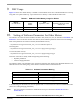


Table 10-2. Start-up Periods
Motor size
x_PER_CMTSTART_US x_PER_TOFFSTART_US
First commutation
period
[µs] [µs] [s]
Slow motor / high load motor
mechanical inertia
>5000 >10000 >10ms
Fast motor / high load motor
mechanical inertia
<5000 <10000 <10ms
Setting of Software Parameters for Other Motors
3-Phase BLDC Motor Control with Sensorless Back-EMF, ADC, Zero Crossing, Rev. 3
54 Freescale Semiconductor
Preliminary
Notes: Slowing down the speed regulator (see Section 10.3.1) helps if a problem with start up (using the
above stated setting) is encountered.
10.2.3 Minimal Zero Commutation of Starting (Back-EMF Acquisition) State
#define x_MIN_ZCROSOK_START 0x02 /* minimal Zero Crossing OK commutation
to finish BLDC starting phase */
This constant x_MIN_ZCROSOK_START determines the minimal number of Zero Crossing OK
commutation to finish the BLDC starting phase.
Notes: It is recommended to use only the value 0x02 or 0x03. If this constant is set too high, the motor control
does not enter the Running state fast enough.
10.2.4 Wrong Zero Crossing
#define x_MAX_ZCROSERR 0x04 /*Maximal Zero Crossing Errors (to stop commutations) */
The constant x_MAX_ZCROSERR is used for control of commuting problems. The application software stops and
starts the motor whenever successive
x_MAX_ZCROSERR commutations (with problematical Zero Crossings)
appear.
Notes: During tuning of the software for other motors, this constant can temporarily be enlarged.
10.2.5 Commutation Proceeding Period
The Commutation proceeding period is the constant time after motor commutation; when Back-EMF Zero
Crossing is not measured (commutation current decay period).
#define x_CONST_PERPROCCMT_US 170.0 /* Period of Commutation proceeding [micros]*/
The unit of this constants is 1 µs.
Notes: This constant needs to be lower then 1/3 of the (minimal) commutation period at motor maximal
speed.