
User Manual


Sensorless Commutation Control
3-Phase BLDC Motor Control with Sensorless Back-EMF, ADC, Zero Crossing, Rev. 3
Freescale Semiconductor 19
Preliminary
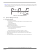
The non-fed phase “branch” voltage U
va
is disturbed at the PWM switching edges. Therefore the presented
BLDC Motor Control application synchronizes the Back-EMF Zero Crossing detection with PWM. The AD
conversion of phase branch voltages is triggered in the middle of PWM pulse. Then the voltage for Back-EMF
is sensed at the time moments because the non-fed phase branch voltage is already stabilized.
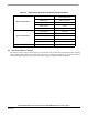
5.4 Sensorless Commutation Control
This section presents sensorless BLDC motor commutation with the Back-EMF Zero Crossing technique.
In order to start and run the BLDC motor, the control algorithm has to go through the following states:
• Alignment
• Starting (Back-EMF Acquisition)
• Running
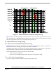
Figure 5-5 shows the transitions between the states. First, the rotor is aligned to a known position without the
position feedback. When the rotor moves, the Back-EMF is induced on the non-fed phase and acquired by the
ADC. As a result, the position is known and can be used to calculate the speed and process the commutation in
the Running state.