FOREWORD This Supplementary Service Manual has been prepared to introduce new service and data for the YZF-R1 2000. For complete service information procedures it is necessary to use this Supplementary Service Manual together with the following manual. YZF-R1 SERVICE MANUAL: 4XV1-AE1 YZF-R1 2000 SUPPLEMENTARY SERVICE MANUAL 1999 by Yamaha Motor Co., Ltd. First Edition, December 1999 Any reproduction or unauthorized use without the written permission of Yamaha Motor Co., Ltd. is expressly prohibited.
EB001000 NOTICE This manual was produced by the Yamaha Motor Company, Ltd. primarily for use by Yamaha dealers and their qualified mechanics. it is not possible to include all the knowledge of a mechanic in one manual. Therefore, anyone who uses this book to perform maintenance and repairs on Yamaha vehicles should have a basic understanding of mechanics and the techniques to repair these types of vehicles.
EB003000 HOW TO USE THIS MANUAL This manual is intended as a handy, easy-to-read reference book for the mechanic. Comprehensive explanations of all installation, removal, disassembly, assembly, repair and check procedures are laid out with the individual steps in sequential order. 1 The manual is divided into chapters. An abbreviation and symbol in the upper right corner of each page indicate the current chapter. Refer to “SYMBOLS”. 2 Each chapter is divided into sections.
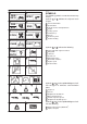
EB004000 1 2 GEN INFO SYMBOLS SPEC 3 4 CHK ADJ ENG 5 6 COOL CARB 7 8 CHAS General information Specifications Periodic checks and adjustments Engine Cooling system Carburetor(-s) Chassis Electrical system Troubleshooting Symbols 10 to 17 indicate the following. 10 10 11 12 13 14 15 16 17 TRBL SHTG 11 12 13 14 15 16 17 18 19 20 24 1 2 3 4 5 6 7 8 9 ELEC 9 21 The following symbols are not relevant to every vehicle. Symbols 1 to 9 indicate the subject of each chapter.
CONTENTS SPECIFICATIONS GENERAL SPECIFICATIONS . . . . . . . . . . . . . . . . . . . . . . . . . . . . . . . . ENGINE SPECIFICATIONS . . . . . . . . . . . . . . . . . . . . . . . . . . . . . . . . . . CHASSIS SPECIFICATIONS . . . . . . . . . . . . . . . . . . . . . . . . . . . . . . . . . ELECTRICAL SPECIFICATIONS . . . . . . . . . . . . . . . . . . . . . . . . . . . . . TIGHTENING TORQUES . . . . . . . . . . . . . . . . . . . . . . . . . . . . . . . . . . . . ENGINE TIGHTENING TORQUES . . . . . . . . . . .
ELECTRICAL INSTRUMENT FUNCTIONS . . . . . . . . . . . . . . . . . . . . . . . . . . . . . . . . . INDICATOR LIGHTS . . . . . . . . . . . . . . . . . . . . . . . . . . . . . . . . . . . . . COOLANT TEMPERATURE WARNING LIGHT . . . . . . . . . . . . . . SPEEDOMETER UNIT . . . . . . . . . . . . . . . . . . . . . . . . . . . . . . . . . . . ELECTRIC STARTING SYSTEM . . . . . . . . . . . . . . . . . . . . . . . . . . . . . STARTER MOTOR . . . . . . . . . . . . . . . . . . . . . . . . . . . . . . . . . . . . . .
GENERAL SPECIFICATIONS SPEC SPECIFICATIONS GENERAL SPECIFICATIONS Item Dimensions Overall length Overall width Overall height Seat height Wheelbase Minimum ground clearance Minimum turning radius Weight Wet (with oil and a full fuel tank) Dry (without oil and fuel) Maximum load (total of cargo, rider, passenger, and accessories) Standard Limit 2,035 mm 2,095 mm (for AUS) 695 mm 1,105 mm 815 mm 1,395 mm 140 mm 3,400 mm 194 kg 175 kg 201 kg –1–
ENGINE SPECIFICATIONS SPEC ENGINE SPECIFICATIONS Item Engine Engine type Displacement Cylinder arrangement Bore stroke Compression ratio Engine idling speed Vacuum pressure at engine idling speed Standard compression pressure (at sea level) Fuel Recommended fuel Fuel tank capacity Total (including reserve) Reserve only Engine oil Lubrication system Recommended oil Standard Limit Liquid-cooled, 4-stroke, DOHC 998 cm3 Forward-inclined parallel 4-cylinder 74 58 mm 11.8 : 1 1,000 1,100 r/min 29.
ENGINE SPECIFICATIONS Item Camshafts Drive system Camshaft cap inside diameter Camshaft journal diameter Camshaft-journal-to-camshaftcap clearance Intake camshaft lobe dimensions SPEC Standard Limit Chain drive (right) 24.500 24.521 mm 24.459 24.472 mm 0.028 0.062 mm Measurement A Measurement B Measurement C Exhaust camshaft lobe dimensions 32.5 32.6 mm 24.95 25.05 mm 7.45 7.65 mm 32.4 mm 24.85 mm Measurement A Measurement B Measurement C Max. camshaft runout 32.
ENGINE SPECIFICATIONS Item Standard Valves, valve seats, valve guides Valve clearance (cold) Intake Exhaust Valve dimensions Head Diameter SPEC 0.11 0.20 mm 0.21 0.
ENGINE SPECIFICATIONS Item Transmission Transmission type Primary reduction system Primary reduction ratio Secondary reduction system Secondary reduction ratio Operation Gear ratios 1st gear 2nd gear 3rd gear 4nd gear 5th gear 6th gear Max. main axle runout Max.
CHASSIS SPECIFICATIONS SPEC CHASSIS SPECIFICATIONS Item Front tire Tire type Size Model (manufacturer) Tire pressure (cold) 0 90 kg 90 197 kg High-speed riding Min. tire tread depth Rear tire Tire type Size Model (manufacturer) Tire pressure (cold) 0 90 kg 90 197 kg High-speed riding Min. tire tread depth Rear brake Brake type Operation Brake pedal position (from the top of the brake pedal to the bottom of the rider footrest bracket) Recommended fluid Brake discs Diameter thickness Min.
CHASSIS SPECIFICATIONS Item Front suspension Suspension type Front fork type Front fork travel Spring Free length Spacer length Installed length Spring rate (K1) Spring stroke (K1) Optional spring available Fork oil Recommended oil Quantity (each front fork leg) Level (from the top of the inner tube, with the inner tube fully compressed, and without the fork spring) Damper adjusting rod locknut distance Spring preload adjusting positions Minimum Standard Maximum Rebound damping adjusting positions Minimum*
CHASSIS SPECIFICATIONS Item Rear suspension Suspension type Rear shock absorber assembly type Rear shock absorber assembly travel Spring Free length Installed length Spring rate (K1) Spring stroke (K1) Optional spring available Standard spring preload gas/air pressure Spring preload adjusting positions Minimum Standard Maximum Rebound damping adjusting positions Minimum* Standard* Maximum* Compression damping adjusting positions Minimum* Standard* Maximum* *with the adjusting screw fully turned in position
ELECTRICAL SPECIFICATIONS SPEC ELECTRICAL SPECIFICATIONS Item Standard Limit System voltage 12 V SSS Ignition system Ignition system type Ignition timing Advanced timing Advancer type Pickup coil resistance/color Transistorized coil ignition unit model (manufacturer) Transistorized coil ignition 5_ BTDC at 1,050 r/min 55_ BTDC at 5,000 r/min Throttle position sensor and electrical 248 372 W/Gy-B TNDF54 (DENSO) SSS SSS SSS SSS SSS SSS Voltage regulator Regulator type Model No-load regulated volt
ELECTRICAL SPECIFICATIONS Item Thermo unit Model (manufacturer) Fuses (amperage quantity) Main fuse Headlight fuse Signaling system fuse Ignition fuse Radiator fan fuse Backup fuse (odometer) Reserve fuse SPEC Standard Limit 5JJ (NIPPON THERMOSTAT) 30 A 1 20 A 1 20 A 1 15 A 1 10 A 1 10 A 1 30 A 1 20 A 1 15 A 1 10 A 1 –10–
TIGHTENING TORQUES SPEC TIGHTENING TORQUES ENGINE TIGHTENING TORQUES Item Cylinder head Cylinder head Generator rotor Oil/water pump assembly driven sprocket cover Air induction system hose Crankcase Crankcase Crankcase Crankcase Ignitor unit Thread size Q’ty y Nut Cap nut Bolt Bolt M10 M10 M10 M6 Clamp Bolt Bolt Bolt Bolt Screw M7 M9 M6 M6 M8 M5 Fastener NOTE: After tightening to 15 Nm (1.5 mSkg), tighten another 45_ 50_ –11– Tightening torque Nm mSkgf 8 2 1 1 50 65 65 12 5.0 6.5 6.5 1.
TIGHTENING TORQUES SPEC CHASSIS TIGHTENING TORQUES Item Thread size Lower ring nut Engine mounting Front mounting bolts Rear upper mounting bolt Rear under mounting bolts Pinch bolts Exhaust pipe bracket Rear master cylinder Tightening Nm m kgf M30 9 0.9 M10 M10 M10 M8 M8 M8 40 55 55 24 24 18 4.0 5.5 5.5 2.4 2.4 1.8 Remarks See NOTE. NOTE: 1. First, tighten the ring nut to approximately 18 Nm (1.8 m kg) with a torque wrench, then loosen the ring nut completely. 2.
LUBRICATION POINTS AND LUBRICANT TYPES SPEC E202000 LUBRICATION POINTS AND LUBRICANT TYPES ENGINE LUBRICATION POINTS AND LUBRICANT TYPES Lubricant Lubrication point Connecting rod bolts and nuts –13–
OIL FLOW DIAGRAMS EB203000 OIL FLOW DIAGRAMS 1 2 3 4 5 6 7 Intake camshaft Exhaust camshaft Crankshaft Oil cooler Oil pipe Oil strainer Oil pump –14– SPEC
OIL FLOW DIAGRAMS 1 Exhaust camshaft 2 Intake camshaft 3 Oil filter –15– SPEC
OIL FLOW DIAGRAMS 1 Cylinder head 2 Crankshaft –16– SPEC
COOLANT FLOW DIAGRAMS EB203000 COOLANT FLOW DIAGRAMS 1 2 3 4 5 6 Thermostat Radiator cap Coolant reservoir Radiator Oil cooler Water jacket joint –17– SPEC
COOLANT FLOW DIAGRAMS 1 2 3 4 Thermostat housing Water pump Radiator Radiator fan –18– SPEC
COOLANT FLOW DIAGRAMS 1 Radiator 2 Thermo unit –19– SPEC
CABLE ROUTING SPEC EB206000 CABLE ROUTING 1 2 3 4 5 Clutch cable Left handlebar switch lead Starter cable Main switch lead Steering cover A Properly insert the meter assembly coupler and rubber boot into the meter assembly. B Route the meter assembly lead through the left side of the headlight housing. C The speedometer lead with not be tighten. D Install the headlight relays onto the headlight housing bridge. E Connect to the right front turn signal connectors.
CABLE ROUTING G Fasten the headlight lead with a plastic clamp at white tape mark. H Fasten the wire harness to the headlight housing boss with a plastic locking tie. I Route the headlight lead through the plastic guide. J Route the throttle cable to the front side of the brake hose. K Route the clutch cable behind the front fork leg. L Make sure that the horn leads face out. M Route the throttle cables and right handlebar switch lead between the lower bracket and steering cover.
CABLE ROUTING Rollover valve (California only) Charcoal canister (California only) Rear brake switch lead Timing chain tensioner. Thermostat assembly breather hose Radiator inlet hose Coolant reservoir breather hose Clutch cable Pickup coil lead A Fasten the starter motor lead to the flame which is just before the side cover stay (0 5 mm) with a plastic clamp. B 0 5 mm 1 2 3 4 5 6 7 8 9 SPEC C Route the rollover-valve-to-fuel-tank hose to the inside of the fuel hose (California only).
CABLE ROUTING 1 Starter cable 2 Air induction system vacuum 3 4 5 6 7 8 9 10 11 hose Air induction system hose Sidestand switch lead Oil level switch lead Clamp Right handlebar switch lead Throttle cables Air guide Air filter case breather hose Coolant reservoir breather hose SPEC Fuel tank overflow hose and fuel tank breather hose Drive chain sprocket cover Coolant hose EXUP servomotor A Route the air filter case breather hose and air induction system hose to the inside of the wire harness.
CABLE ROUTING C D E F SPEC To the connector cover. J Route the sidestand switch lead and oil level switch Route the seat lock cable over the wire harness. lead to the inside of the drive sprocket cover. Fasten the wire harness with a plastic clamp. K Do not crush the water pump breather hose and Make sure the rear flasher light lead coupler and plastic clip. tail light lead coupler in the rubber cover.
CABLE ROUTING N Pass the fuel tank breather hose and the air filter Q drain hose through the inside of the coolant hose. R No hose must be inserted into the under cowling. S O Pass the air filter drain hose and the coolant reservoir hose through the inside of the coolant hose and route the leading ends to the bottom of the T coolant hose. The leading ends must not protrude from the under cowling.
CABLE ROUTING Speed sensor lead Charcoal canister (California only) EXUP cables EXUP A Route the EXUP cables behind the cross tube. B Route the neutral switch lead direct to upper right side. C Route the EXUP cables on the outside of the engine mount. 1 2 3 4 SPEC D Route the EXUP cables behind the swing arm head pipe. E Fasten the EXUP cables and engine mount with a plastic locking tie.
CABLE ROUTING 1 2 3 4 5 6 7 8 9 10 11 12 Headlight sub-wire harness Left handlebar switch lead Main switch lead Starter cable Right handlebar switch coupler Throttle cables Engine air vent hose EXUP servomotor coupler Air vent surge tank Starter motor lead Pickup coil coupler Fuel pump coupler 13 14 15 16 17 18 19 20 21 22 23 24 SPEC Neutral switch connector Battery negative lead Rear brake switch coupler Speed sensor coupler EXUP cable Fuel tank overflow hose Fuel tank breather hose (except for Califor
CABLE ROUTING 25 26 27 28 29 30 31 32 33 34 35 Engine oil level switch lead Air filter case drain hose Air induction system hose Ignition coil Cover Rivet Screw Coupler Main harness Frame Rear fender –28– SPEC
CABLE ROUTING A Make sure the headlight lead in the rubber cover. B Route the horn lead over the horn bracket and make sure that the lead has no slack. C Do not cross the throttle cables and right handlebar switch lead. D Route the thermo switch lead through the steel band on the radiator. E Fasten the main harness and thermo switch lead with a plastic clamp. Insert the plastic clamp into the hole on the frame. F Route the ignition coil sub-wire harness under the throttle position sensor.
CABLE ROUTING SPEC L Fasten the fuel pump lead, speed sensor lead, tank breather hose have each white mark. neutral switch lead, rear brake light lead, fuel send- S 30 mm (1.17 in) er lead, starter motor lead and EXUP cable with a T Fasten the battery positive lead and starter motor plastic clamp. lead with a plastic locking tie. M 125 mm (4.88 in) U Route the rear flasher light lead in the hole on the N 50 mm (1.95 in) rear fender. O To the fuel cock.
CABLE ROUTING X Fasten the main harness with a plastic band on the rear fender. Y Position the ground coupler over the main harness. Z Route the ground lead under the starter relay lead. A’ Fasten the starter relay lead, ground lead, starting circuit cutoff relay lead, alam lead and main harness with a plastic clamp. Route the clamp end to outside, and insert it between wire harness and fender. B’ Route the taillight leads through the rear fender.
CABLE ROUTING I’ Fasten the main harness with a plastic clamp. Insert the plastic clamp into the hole on the frame. J’ Route the charcoal canister hose under the engine air vent hose, coolant reservoir tank breather hose and all of leads. (California only) K’ Fasten the wire harness with a plastic clamp and then insert the clamp into the frame. L’ To the radiator fan motor. M’ Route the main harness and fan motor lead into the hole on the air intake guide.
PERIODIC MAINTENANCE AND LUBRICATION INTERVALS CHK ADJ EB300000 PERIODIC CHECKS AND ADJUSTMENTS INTRODUCTION This chapter includes all information necessary to perform recommended checks and adjustments. If followed, these preventive maintenance procedures will ensure more reliable vehicle operation, a longer service life and reduce the need for costly overhaul work. This information applies to vehicles already in service as well as to new vehicles that are being prepared for sale.
PERIODIC MAINTENANCE AND LUBRICATION INTERVALS No No. ITEM CHECKS AND MAINTENANCE JOBS After the first 1,000 km CHK ADJ Every Every 10,000 km 20,000 km Annual check 16 * Chassis fasteners S Make sure that all nuts, bolts and screws are properly tightened. S Tighten if necessary. 17 Sidestand S Check operation. S Lubricate and repair if necessary. 18 * Sidestand switch S Check operation. S Replace if necessary. 19 * Front fork S Check operation and for oil leakage.
COWLINGS CHK ADJ EB302020 COWLINGS 5 Nm (0.5 m kg) Order 1 2 3 4 5 6 7 8 9 Job/Part Removing the cowlings Rider and passenger seats Rear cowling Bottom cowling Front cowling inner panel (left) Front cowling inner panel (right) Left side cowling Right side cowling Windshield Rear view mirror Front cowling Q’ty Remarks Remove the parts in the order listed. Refer to “SEATS”. 1 1 1 1 1 1 1 2 1 Front installation, reverse the removal procedure.
AIR FILTER CASE AND IGNITION COIL PLATE CHK ADJ EB302040 AIR FILTER CASE AND IGNITION COIL PLATE Order 1 2 3 4 5 6 7 8 9 10 11 Job/Part Removing the air filter case and ignition coil plate Rider seat and fuel tank Crankcase breather hose Air filter case breather hose Air induction system hose Clamp screw Bolt Air filter case Quick fastener Ignition coil coupler Spark plug cap Ignition coil plate/ignition coil Rubber baffle Q’ty Remarks Remove the parts in the order listed.
ENGINE CHK ADJ OVERHAULING THE ENGINE AIR INDUCTION SYSTEM 4 Nm (0.4 m kg) Order 1 2 3 4 Job/Part Q’ty Removing the air induction system Air induction pipe Air cutoff valve Carburetor joint hose Air intake hose Remarks Remove the parts in the order listed. 4 1 1 1 For installation, reverse the removal procedure.
ENGINE ENG ENGINE 24 Nm (2.4 m kg) 40 Nm (4.4 m kg) 55 Nm (5.5 m kg) 40 Nm (4.0 m kg) 55 Nm (5.5 m kg) Order 24 Nm (2.4 m kg) Job/Part Q’ty Remove the parts in the order listed. NOTE: Place a suitable stand under the frame and engine. Removing the engine 1 2 3 4 5 6 7 8 9 Pinch bolt Right front mounting bolt Washer Spacer Left front mounting bolt Washer Self-locking nut Rear mounting bolt Spacer Remarks 2 1 1 1 2 2 2 2 1 Loosen. For installation, reverse the removal procedure.
ENGINE ENG EB400700 INSTALLING THE ENGINE 1. Install: engine assembly a. Install the spacer 1 to the frame. b. Temporally tighten the right front mounting bolt 2 , left front mounting bolt 3 , and washers 4 5 . c. Lubricate the rear mounting bolts 6 7 threads with lithium soap base grease. d. Install the rear mounting bolts 6 7 and self locking nut 8 9 . e. Tighten the self locking nut 8 , and then tighten the self locking nut 9 . f. Tighten the pinch bolt 10 . g. Tighten the left mounting bolt 3 . h.
CYLINDER HEAD ENG EB402000 CYLINDER HEAD 50 Nm (5.0 m kg) 65 Nm (6.5 m kg) 12 Nm (1.2 m kg) Order 1 2 3 Job/Part Removing the cylinder head Engine Intake and exhaust camshafts Cylinder head Cylinder head gasket Dowel pin Q’ty Remarks Remove the parts in the order listed. Refer to “ENGINE”. Refer to “CAMSHAFTS”. 1 1 2 For installation, reverse the removal procedure.
CRANKCASE ENG CRANKCASE 10 Nm (1.0 m kg) 10 Nm (1.0 m kg) Order 1 2 3 4 5 Job/Part Q’ty Separating the crankcase Engine Cylinder head Pickup coil and pickup coil rotor Stator coil assembly Clutch housing and starter clutch idle gear Oil/water pump assembly Timing chain Crankshaft sprocket Pin Oil/water pump assembly drive chain guide Oil/water pump assembly drive chain Remarks Remove the parts in the order listed. Refer to “ENGINE”. Refer to “CYLINDER HEAD”. Refer to “PICKUP COIL”.
CRANKCASE ENG 10 Nm (1.0 m kg) 10 Nm (1.0 m kg) Order 6 7 8 9 10 Job/Part Oil/water pump assembly drive sprocket Washer Plate Lower crankcase Dowel pin Q’ty Remarks 1 1 1 1 3 For installation, reverse the removal procedure.
CRANKCASE ENG EB412743 ASSEMBLING THE CRANKCASE 1. Lubricate: crankshaft journal bearings (with the recommended lubricant) Recommended lubricant Engine oil 2. Apply: sealant (onto the crankcase mating surfaces and the groove a of the oil baffle plate) Yamaha bond No. 1215 90890-85505 NOTE: Do not allow any sealant to come into contact with the oil gallery or crankshaft journal bearings. Do not apply sealant to within 2 X 3 mm of the crankshaft journal bearings. 3. Install: dowel pin 4.
CRANKCASE ENG 6. Install: S lower crankcase 1 (onto the upper crankcase 2 ) CAUTION: Before tightening the crankcase bolts, make sure that the transmission gears shift correctly when the shift drum assembly is turned by hand. 7. Install: S crankcase bolts NOTE: S Lubricate the bolt threads with engine oil. S Install a washer on bolts 1 X 10 . S Tighten each bolt at 15 Nm in the tightening sequence cast on the crankcase. S Loosen each bolt one time and tighten 15 Nm in the same sequence.
RADIATOR COOL EB500000 COOLING SYSTEM RADIATOR 10 Nm (1.0 m kg) 20 Nm (2.0 m kg) 9 Nm (0.9 m kg) 23 Nm (2.3 m kg) 4.5 Nm (0.45 m kg) Order Job/Part Q’ty Remove the parts in the order listed. Refer to “SEATS” and “FUEL TANK” in chapter 3. Refer to “AIR FILTER CASE AND IGNITION COIL PLATE” in chapter 3. Refer to “COWLINGS” in chapter 3. Refer to “ENGINE” in chapter 4. Drain. Refer to “CHANGING THE COOLANT” in chapter 3.
RADIATOR COOL 10 Nm (1.0 m kg) 20 Nm (2.0 m kg) 9 Nm (0.9 m kg) 23 Nm (2.3 m kg) 4.5 Nm (0.45 m kg) Order 5 6 7 8 9 10 11 12 13 14 15 Job/Part Thermo unit Thermostat assembly breather hose Radiator inlet hose Oil cooler outlet hose Water pump breather hose Radiator outlet hose Water pump inlet pipe Radiator fan motor coupler Horn bracket Radiator Radiator fan Q’ty 1 1 1 1 1 1 1 1 1 1 1 Remarks Disconnect. Disconnect. Disconnect. For installation, reverse the removal procedure.
AIR INDUCTION SYSTEM CARB EAS00507 CARBURETORS AIR INDUCTION SYSTEM AIR INJECTION The air induction system burns unburned exhaust gases by injecting fresh air (secondary air) into the exhaust port, reducing the emission of hydrocarbons. When there is negative pressure at the exhaust port, the reed valve opens, allowing secondary air to flow into the exhaust port. The required temperature for burning the unburned exhaust gases is approximately 600 to 700_C.
AIR INDUCTION SYSTEM EAS00509 AIR INDUCTION SYSTEM DIAGRAMS 1 2 3 4 Reed valve Air cleaner Air cutoff valve Carburetor joint (cylinder #1) A B D D E –48– To the air cutoff valve To cylinder #1 To cylinder #2 To cylinder #3 To cylinder #4 CARB
AIR INDUCTION SYSTEM CARB EAS00510 CHECKING THE AIR INDUCTION SYSTEM 1. Check: hoses Loose connection Connect properly. Cracks/damage Replace. pipes Cracks/damage Replace. 2. Check: fibre reed 1 fibre reed stopper reed valve seat Cracks/damage Replace. 3. Measure: fibre reed bending limit a Out of specification Replace the reed valve. Fibre reed bending limit 0.4 mm 1 Surface plate 4. Check: air cutoff valve Cracks/damage Replace.
FRONT WHEEL AND BRAKE DISCS CHAS EB700002 CHASSIS FRONT WHEEL AND BRAKE DISCS 6 Nm (0.6 m kg) 72 Nm (7.2 m kg) 40 Nm (4.0 m kg) 18 Nm (1.8 m kg) Order Job/Part Q’ty Remove the parts in the order listed. NOTE: Place the motorcycle on a suitable stand so that the front wheel is elevated.
FRONT WHEEL AND BRAKE DISCS CHAS EB700725 INSTALLING THE FRONT WHEEL 1. Lubricate: wheel axle oil seal lips Recommended lubricant Lithium soap base grease 2. Install: brake discs 1 18 Nm (1.8 m kg) NOTE: Apply LOCTITE 648 to the threads of the brake disc bolts. Tighten the brake disc bolts in stages and in a crisscross pattern. 3. Tighten: wheel axle 1 wheel axle pinch bolt 1 72 Nm (7.2 m kg) 23 Nm (2.
FRONT AND REAR BRAKES CHAS EB702202 FRONT AND REAR BRAKES REAR BRAKE MASTER CYLINDER AND BRAKE FLUID RESERVOIR 5 Nm (0.5 m kg) 30 Nm (3.0 m kg) 23 Nm (2.
INSTRUMENT FUNCTIONS ELEC ELECTRICAL INSTRUMENT FUNCTIONS INDICATOR LIGHTS Neutral indicator light “ ” This indicator light comes on when the transmission is in the neutral position. ” High beam indicator light “ This indicator comes on when the headlight high beam is used. Turn signal indicator light “ ” This indicator light flashes when the turn signal switch is pushed to the left or right.
INSTRUMENT FUNCTIONS ELEC COOLANT TEMPERATURE WARNING LIGHT 1 Coolant temperature gauge 2 Coolant temperature warning light “ Coolant temperature warning light “ ” This warning light comes on when the engine overheats. When this occurs, stop the engine immediately and allow the engine to cool. The electrical circuit of the warning light can be checked according to the following procedure. 1. Set the engine stop switch to “ ” and turn the key to “ON”. 2.
INSTRUMENT FUNCTIONS ELEC SPEEDOMETER UNIT The speedometer unit is equipped with the following: a digital speedometer (which shows riding speed) an odometer (which shows the total distance traveled) two tripmeters (which show the distance traveled since they were last set to zero) a fuel reserve tripmeter (which shows the distance traveled on the fuel reserve) a clock 1 Speedometer 2 Odometer / tripmeter / fuel reserve tripmeter / clock 3 “RESET” button 4 “SELECT” button Odometer and tripmeter
INSTRUMENT FUNCTIONS ELEC Clock mode To change the display to the clock mode, push the “SELECT” button for at least one second. To change the display back to the odometer modes, push the “SELECT” button. To set the clock: 1. Push the “SELECT” button and “RESET” button together for at least two seconds. 2. When the hour digits start flashing, push the “RESET” button to set the hours. 3. Push the “SELECT” button, and the minute digits will start flashing. 4. Push the “RESET” button to set the minutes. 5.
ELECTRIC STARTING SYSTEM ELEC ELECTRIC STARTING SYSTEM STARTER MOTOR 5 Nm (0.5 m kg) 7 Nm (0.7 m kg) Order 1 2 3 4 Job/Part Removing the starter motor Rider seat Fuel tank Left side cowling EXUP servomotor Throttle stop screw Starter motor lead Starter motor assembly Q’ty Remarks Remove the parts in the order listed. Refer to “SEATS” in chapter 3. Refer to “FUEL TANK” in chapter 3. Refer to “COWLINGS” in chapter 3. 1 1 1 1 For installation, reverse the removal procedure.
ELECTRIC STARTING SYSTEM ELEC EB803501 5 Nm (0.5 m kg) Order 1 2 3 4 5 6 7 8 9 Job/Part Disassembling the starter motor Starter motor rear cover Bearing Starter motor yoke O-ring Armature assembly Brush Brush holder Starter motor front cover Bearing Q’ty Remarks Disassembly the parts in the order listed.
ELECTRIC STARTING SYSTEM ELEC EB803511 Checking The Starter Motor 1. Check: S commutator Dirt Clean with 600 grit sandpaper. 2. Measure: S commutator diameter a Out of specification Replace the starter motor. Min. commutator diameter 23.5 mm 3. Measure: S mica undercut a Out of specification Scrape the mica to the proper measurement with a hacksaw blade which has been grounded to fit the commutator. Mica undercut 1.5 mm NOTE: The mica must be undercut to ensure proper operation of the commutator.
ELECTRIC STARTING SYSTEM ELEC 5. Measure: brush length a Out of specification Replace the brushes as a set. Min. brush length 3.65 mm 6. Measure: brush spring force Out of specification Replace the brush springs as a set. Brush spring force 5.28 X 7.92 N 7. Check: gear teeth Damage/wear Replace the gear. 8. Check: bearing oil seal Damage/wear Replace the defective part(-s). EB803701 Assembling The Starter Motor 1.
ELECTRIC STARTING SYSTEM ELEC 3. Install: starter motor yoke 2 O-rings 1 New starter motor rear cover 3 bolts 5 Nm (0.5 m kg) NOTE: Align the match marks a on the starter motor yoke with the match marks b on the front and rear covers.
COOLING SYSTEM EB807000 COOLING SYSTEM CIRCUIT DIAGRAM 1 5 6 22 28 48 49 50 Main switch Battery Main fuse Thermo unit Combination meter Radiator fan motor Radiator fan motor relay Radiator fan motor fuse –62– ELEC
COOLING SYSTEM EB807010 ELEC EB802401 TROUBLESHOOTING 2. Battery S The radiator fan motor fails to turn. S The coolant temperature meter needle fails to move when the engine is warm. S Check the condition of the battery. Refer to “CHECKING AND CHARGING THE BATTERY” in chapter 3. CAUTION: Open-circuit voltage 12.
COOLING SYSTEM EB807400 ELEC EB807402 5. Fan motor relay 7. Thermo unit S Disconnect the fan motor relay coupler. S Connect the pocket tester (Ω 1) and battery (12V) to the fan motor relay coupler as shown. S Remove the thermo unit from the radiator. S Connect the pocket tester (Ω 1) to the thermo unit 1 as shown. S Immerse the thermo unit in a container filled with coolant 2 . NOTE: Make sure that the thermo unit terminals do not get wet.
COOLING SYSTEM Does the thermo unit operate properly as described above? YES NO Replace the thermo unit. EB807403 8. Wiring Check the entire cooling system’s wiring. Refer to “CIRCUIT DIAGRAM”. Is the cooling system’s wiring properly connected and without defects? YES This circuit is OK. NO Properly connect or repair the cooling system’s wiring.
SELF-DIAGNOSIS ELEC EB812000 SELF-DIAGNOSIS The YZF-R1 features a self-diagnosing system for the following circuit(-s): throttle position sensor EXUP speed sensor fuel level warning light If any of these circuits are defective, their respective condition codes will be displayed on the tachometer when the main switch is set to “ON” (irrespective of whether the engine is running or not) Circuit Throttle position sensor Defect(-s) Disconnected Short-circuit Locked EXUP Improper connection
SELF-DIAGNOSIS ELEC EB812010 2. Speed sensor TROUBLESHOOTING Place the motorcycle on a suitable stand so that the rear wheel is elecated. Connect the pocket tester (DC 20V) to the speed sensor connector. The tachometer starts to display the selfdiagnosis sequence. Check: 1. speed sensor 2. fuel level warning light NOTE: Troubleshoot tool(-s). with the Tester (+) lead ³ White 1 terminal Tester (–) lead ³ Body earth following special Pocket tester 90890-03112 1.
YZF-R1 WIRING DIAGRAM (For EUR) COLOR CODE B ..... Br . . . . Ch . . . Dg . . . G .... Gy . . . L ..... O .... P ..... R..... black brown chocolate dark green green gray blue orange pink red Sb . . . . W .... Y ..... B/ L . . . B/ R . . . B/ W . . B/ Y . . . Br/ L . . Br/ R . . Br/ W . sky blue white yellow black/ blue black/ red black/ white black/ yellow brown/ blue brown/ red brown/ white G/R . . G/W . . G/Y . . L/B . . . L/R . . . L/W . . L/Y . . . O/R . . R/ B . . . R/ G . .
YZF-R1 WIRING DIAGRAM (For OCE) COLOR CODE B ..... Br . . . . Ch . . . Dg . . . G .... Gy . . . L ..... O .... P ..... R..... black brown chocolate dark green green gray blue orange pink red Sb . . . . W .... Y ..... B/ L . . . B/ R . . . B/ W . . B/ Y . . . Br/ L . . Br/ R . . Br/ W . sky blue white yellow black/ blue black/ red black/ white black/ yellow brown/ blue brown/ red brown/ white G/R . . G/W . . G/Y . . L/B . . . L/R . . . L/W . . L/Y . . . O/R . . R/ B . . . R/ G . .