
Service manual


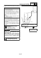

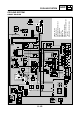
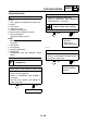
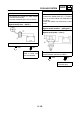

Table Of Contents

8 - 38
– +
ELEC
SIGNALING SYSTEM
EAS00806
4. The speedometer fails to operate.
YES
NO
YES
NO
1. Speed sensor
• Connect the pocket tester (DC 20 V) to the
speed sensor coupler (wire harness side)
as shown.
Positive tester probe
→
gray
1
Negative tester probe
→
gray/black
2
• Set the main switch to “ON”.
• Elevate the front wheel and slowly rotate
it.
• Measure the voltage (DC 5 V) of gray and
gray/black. With each full rotation of the
front wheel, the voltage reading should
cycle from 0.6 V to 4.8 V to 0.6 V to 4.8 V.
• Does the voltage reading cycle correctly?
Replace the speed
sensor.
2
1
Gy
Gy/B
Gy/R
R
B
L
2. Voltage
• Connect the pocket tester (DC 20 V) to the
meter assembly coupler as shown.
Positive tester probe
→
gray
1
Negative tester probe
→
black
2
• Set the main switch to “ON”.
• Measure the voltage (DC 5 V) of gray
1
on the meter assembly coupler.
• Is the voltage within specification?
This circuit is OK. Replace the meter
assembly.
12
G/L
YB Dg
Sb
G/R
O/W
B
Br/GBr/G
Gy Br
Ch
R/L
Gy/B
Gy/
R