
User Guide


2A-36
Chapter 2 Part A Engine, clutch and transmission (XV535 models)
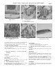
16.34 On models so equipped, align the
double notches in the friction plates (1)
with the marks on the clutch housing (2) .
16.35 ... if tight friction plates impede
clutch movement, align the single
notches (3) with the marks (2)
16.37a Loosen the adjuster
locknut (arrow)
16.37b Align the clutch lever mark with
the mark on the crankcase
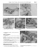
16.38a Remove the snap-ring ,
16.3&b ... and pry out the seal
16.38c Make sure the dowels are in position (arrows) and install
the gasket
32 If you removed the clutch damper, reverse Step 13 to install it.
The OUTSIDE mark on the seat spring faces out (away from the
engine). Make sure the wire ring is securely seated in its groove in the
clutch boss.
33 Coat the pushrods and steel ball with multipurpose grease. Install
the long pushrod and ball in the engine and the short pushrod in the
pressure plate (see illustrations 16.6b, 16.6a and 16.5b).
34 Coat one of the friction plates with engine oil and install it in the
clutch housing so its double notch aligns with the embossed marks on
the clutch housing (see illustration). If there aren't any visible marks
on the clutch housing, align the double notches on all of the friction
plates with each other. Engage the tabs on the friction plate with the
slots in the clutch housing.
35 Coat a metal plate with engine oil and install it on top of the
friction plate with its rounded side in. Continue to install alternate
friction and metal plates, coated with engine oil (a friction plate is the
last one installed). Align the double notch on each remaining friction
plate with the clutch housing marks (if equipped) or with the double
notches on the previously installed friction plates. Note: If any of the
friction plates fit tightly in the clutch housing, remove all of the friction
and metal plates, then reinstall them so the single notches are aligned
with the clutch housing marks (see illustration).
36 Install the pressure plate, springs and screws. Tighten the screws
evenly in a criss-cross pattern to the torque listed in this Chapter's
Specifications.
37 Loosen the locknut on the clutch mechanism freeplay adjuster
(see illustration). Push the lever by hand toward the front of the
engine as far as it will go, then note the positions of the lever mark and
the match mark on the crankcase (see illustration). If they aren't
aligned, turn the adjuster in or out until they are, then tighten the
locknut.
38 Remove the snap-ring and pry the seal out of the clutch cover
(see illustrations). Tap in a new seal with a socket the same diameter
as the seal, then install a new snap-ring. Make sure the clutch cover
dowels are in position and install a new gasket (see illustration).