
User Guide


Chapter 1 Tune-up and routine maintenance
1-17
14.6 Separate the housing halves and
take the filter element out
14.7a Check the seal between the filter
housing and the frame ...
14.7b ... and the seals inside the filter
housing; replace them if they're
deteriorated or brittle
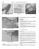
14.9 Loosen the clamp bolt and remove
the Allen bolts, then detach the air filter
case from the motorcycle
14.10a Remove the cover from the inside
of the case
14.10b Remove the filter element
retaining screw, detach the mounting tab
and lift out the element
1984 and later XV700 through 1100 models
Refer to illustrations 14.9, 14.10a and 14.10b
8 Remove the fuel tank (see Chapter 3).
9 Loosen the air duct clamp bolt and remove the mounting bolts,
then take the air filter case off the motorcycle (see illustration).
10 Remove the air filter case cover (see illustration). Remove the
element mounting screw and take the element out (see illustration).
All models
11 Tap the element on a hard surface to shake out dirt.' If
compressed air is available, use it to clean the element by blowing
from the inside out. If the element is extremely dirty or torn, or if dirt
can't be blown or tapped out, replace it with a new one.
12 Reinstall the filter by reversing the removal procedure. Make sure
the element is seated properly in the filter housing before installing the
cover.
13 Install all components removed for access.
15 Cylinder compression - check
1 Among other things, poor engine performance may be caused by
leaking valves, incorrect valve clearances, a leaking head gasket, or
worn pistons, rings and/or cylinder walls. A cylinder compression
check will help pinpoint these conditions and can also indicate the
presence of excessive carbon deposits in the cylinder heads.
2 The only tools required are a compression gauge and a spark
plug wrench. Depending on the outcome of the initial test, a squirt-
type oil can may also be needed.
3 Start the engine and allow it to reach normal operating
temperature.
4 Support the bike securely so it can't be knocked over during this
procedure.
5 Remove the spark plugs (see Section 16, if necessary). Work
carefully - don't strip the spark plug hole threads and don't burn your
hands.
6 Disable the ignition by unplugging the primary wires from the coils
(see Chapter 4). Be sure to mark the locations of the wires before
detaching them.
7 Install the compression gauge in one of the spark plug holes.
8 Hold or block the throttle wide open.
9 Crank the engine over a minimum of four or five revolutions (or
until the gauge reading stops increasing) and observe the initial
movement of the compression gauge needle as well as the final total
gauge reading. Repeat the procedure for the other cylinder and
compare the results to the value listed in this Chapter's Specifications.
10 If the compression in both cylinders built up quickly and evenly to
the specified amount, you can assume the engine upper end is in
reasonably good mechanical condition. Worn or sticking piston rings
and worn cylinders will produce very little initial movement of the
gauge needle, but compression will tend to build up gradually as the
engine spins over. Valve and valve seat leakage, or head gasket
leakage, is indicated by low initial compression which does not tend to
build up.
11 To further confirm your findings, add a small amount of engine oil