
User Guide


8B-16
Chapter 8 Part B Electrical system (XV700-1100 models)
28.13a The legs on the intermediate gear fit into the gaps
between the rotor springs
28.13b Make sure the mark on the gear aligns with
the hole in the rotor
13 Installation is the reverse of the removal steps, with the following
additions:
a) If the intermediate gear was removed from the back of the rotor,
position the three pairs of rotor springs with gaps between them
and press the gear into position. Make sure its alignment mark is
lined up with the sighting hole in the rotor (see illustrations).
b) Be sure to reinstall the Woodruff key. Caution: Make sure no
metal objects have stuck to the magnets inside the rotor.
28.13c Tighten the rotor nut to the specified torque
c) Aligning the rotor and intermediate gear must be done in a
specific way. Refer to the timing gear installation procedures in
Part B of Chapter 2.
d) Tighten the rotor nut to the torque listed in this Chapter's Specifi-
cations (see illustration).
Regulator/rectifier
Refer to illustration 28.14
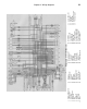
14 On 1981 through 1983 models, the regulator/rectifier unit is
mounted on the rear subframe (see illustration). On 1984 and later
models, it is mounted inboard of the luggage box behind the left side
cover.
15 Follow the wiring harness from the regulator/rectifier to the
connector. Disconnect the electrical connector and remove the
regulator/rectifier mounting fasteners.
16 Installation is the reverse of the removal steps.
29 Oil level switch - removal, check and installation
Refer to illustrations 29.3a and 29.3b
Removal
1 Drain the engine oil (see Chapter 1).
2 The oil level switch is mounted in the bottom of the crankcase.
Note how its wiring harness is routed, then unplug the electrical
connector.
3 Remove the cover, then-unscrew the switch (see illustrations).
Check
4 Connect an ohmmeter between the terminals of the switch
harness. With the switch in its normal installed position, the ohmmete
r
should indicate infinite resistance.
5 Turn the switch upside down. The ohmmeter should now reac
zero ohms.
6 If the ohmmeter doesn't give the correct indication in Step 4 or 5
replace the switch.
Installation
7 Installation is the reverse of the removal steps. Use a new sealing
washer and tighten the switch to the torque listed in this Chapter's
Specifications.
30 Starter clutch - removal, inspection and installation
1 Two different starter clutch designs are used, one on 1981
through 1985 XV750, XV700 and XV920 models, the other on XV100C
XV1100, and 1986 and later XV700 and XV750 models.
28.14 The voltage regulator/rectifier on 1981 through 1983
models is mounted on the rear subframe