
User Guide


6A-2
Chapter 6 Part A Brakes, wheels and tires (XV535 models)
Wheels and tires
Wheel runout
Radial (up-and-down) 2.0 mm (0.08 inch)
Axial (side-to-side) 2.0 mm (0.08 inch)
Tire pressures See Chapter 1
Tire sizes
Front 3.00S-19 4PR
Rear 140/90-15M/C 70S
Torque specifications
Caliper lower mounting bolt (to bracket) 18 Nm (13 ft-lbs)
Caliper bracket bolts (to fork leg) . 35 Nm (25 ft-lbs)
Front axle 58 Nm (42 ft-lbs)
Front axle pinch bolt 20 Nm (14 ft-lbs)
Brake disc mounting bolts 20 Nm (14 ft-lbs)*
Union (banjo fitting) bolts 26 Nm (19 ft-lbs)
Master cylinder mounting bolts 9 Nm (6.5 ft-lbs)
Rear axle nut
1987 and 1988 models 105 Nm (75 ft-lbs)
1989-on models 107 Nm (77, ft-lbs)
Rear axle pinch bolt 16 Nm (11 ft-lbs)
Rear wheel clutch hub bolts
1987 and 1988 models 69 Nm. (50 ft-lbs)
1989-on models 62 Nm (45 ft-lbs)
Brakerod nuts 20 Nm (14 ft-lbs)**
*Use new lockwashers.
**Use new cotter pins.
1 General information
The models covered in this Chapter are equipped with a hydraulic disc
brake at the front and a mechanical drum brake at the rear.
Ail XV535 models are equipped with wire spoke wheels and tubed
tires.
Caution: Disc brake components rarely require disassembly. Do
not disassemble components unless absolutely necessary. If any
hydraulic brake line connection in the system is loosened, the entire
system should be disassembled, drained, cleaned and then properly
filled and bled upon reassembly. Do not use solvents on internal brake
components. Solvents will cause seals to swell and distort. Use only
clean brake fluid, brake cleaner or alcohol for cleaning. Use care when
working with brake fluid as it can injure your eyes and it will damage
painted surfaces and plastic parts.
2 Brake pads - replacement
Warning: The dust created by the brake system may contain asbestos,
which is harmful to your health. Never blow it out with compressed air
and don't inhale any of it. An approved filtering mask should be worn
when working on the brakes.
Refer to illustrations 2.2a, 2.2b, 2.3a, 2.3b, 2.3c, 2.6a and 2.6b
1 Support the bike securely so it can't be knocked over during this
procedure.
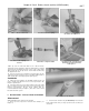
2 Remove the caliper lower mounting bolt (see illustration). Rotate
the caliper up to expose the pads (see illustration).
3 Remove the pads and pad springs (see illustrations). Measure
the amount of friction material left on the pads and replace them as a
pair if worn, fouled with oil or damaged in any way.
4 Check the condition of the brake discs (see Section 4). If they are
2.2a Remove the lower mounting bolt
from the caliper ...
2.2b ... and pivot the caliper up to expose
the pads
2.3a Remove the pads; the rounded edge
of each pad (arrow) faces the rear of
the motorcycle