
User Guide


Chapter 3 Part B Fuel and exhaust systems (XV700-1100 models)
3B-7
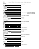
7.1 Carburetors (XV700-1100,1981 through 1987 US and
all UK models) - exploded view
1 Vacuum chamber cover screws
2 Lockwashers
3 Upper bracket
4 Vacuum chamber cover
5 Piston spring
6 Vacuum piston
7 Jet needle
8 Spring
9 Plastic Allen screw
10 Needle jet
11 Choke control plate
12 Cotter pin
13 Washer
14 Screw
15 Lockwasher
16 Pilot adjustment screw
17 Spring
18 Spring
19 Screw
20 Washer
21 Throttle stop screw {rear carburetor)
22 Locknut
23 Main jet
24 Sealing washer
25 Pilot jet
26 Needle valve and seat
27 Sealing washer
28 Floats
29 Float pivot pin
30 Gasket
31 Float chamber
32 Drain screw
33 Float chamber screws
34 Lockwashers
35 Lower bracket
36 Screws
37 Lockwashers
38 Throttle linkage pivot
39 Washers
40 Bushing
41 E-clip
42 Choke control plate
43 Bushing
44 Throttle stop screw
45 Spring
46 Screw
47 Lockwasher
48 Cap
49 Choke plunger retaining plug
50 Choke plunger
51 Spring
52 Washer
53 Choke linkage rod
54 Cotter pin
55 Washer
56 Pilot screw
57 O-ring
58 Spring
work in a garage where a natural gas-type appliance (such as a water
heater or clothes dryer) is present. If you spill any fuel on your skin,
rinse it off immediately with soap and water. When you perform any
kirfd of work on the fuel system, wear safety glasses and have a fire
extinguisher suitable for class B type fires (flammable liquids) on hand.
1981 through 1987 US and all UK models
Disassembly
Refer to illustrations 7.1, 7.3, 7.4, 7.5a, 7.5b, 7.6, 7.7, 7.8, 7.9, 7.10,
7.11, 7.12a, 7.12b, 7.13, 7.14a, 7.14b and 7.15
1 Remove the carburetors from the machine as described in
Section 6. Set the assembly on a clean working surface. Note: Work
on one carburetor at a time to avoid getting parts mixed up (see
illustration). Most disassembly and cleaning procedures can be
accomplished without separating the carburetors.