
User Guide


2B-38
Chapter 2 Part B Engine, clutch and transmission (XV700-1100 models)
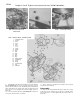
21.4a Right crankcase half components
7 Crankshaft bearing
2 Transmission bearings
3 Middle gear bearings
4 O-ring
5 Oil pressure relief valve
6 Oil level switch
21.4b Use a slide hammer to remove the bearings if they don't lift
out easily ...
21.4c ... the slide hammer's puller attachment fits behind the
bearing like this
4 Spin the bearings in the crankcase halves (see illustration) with
fingers and check for looseness, roughness or excessive noise.
Replace the bearings if these conditions are found. Remove the
bearings with fingers, or if necessary, with a slide hammer (see
illustrations).
5 Remove the oil seal from behind the transmission mainshaft
bearing in the left side of the crankcase (see illustration). Make sure
the oil passages behind the seal is clear and the bearing bore is clean
(see illustration), then tap in a new oil seal.
6 Set the new bearings in their bores, then tap them into position
with a bearing driver or a socket that bears against the bearing outer
race (see illustrations). Note: Special equipment is required for
access to the middle gear bearings.
22 Oil pressure relief valve - removal, inspection and
installation
Refer to illustrations 22.3, 22.4 and 22.6
1 Disassemble the crankcase (see Section 20).
2 Work the oil pressure relief valve out of the crankcase (it's held in
by an O-ring) (see illustration 21.4a).
3 Push the plunger into the relief valve and check for free
movement (see illustration). If the valve sticks, perform Steps 4 and 5
to disassemble and inspect it.
4 Straighten the cotter pin and pull it out (see illustration). Remove
the spring retainer, spring and plunger.
5 Check all parts for wear and damage. Clean the parts thoroughly,
reassemble the valve and recheck its movement. If the valve still sticks,