
User Guide


2B-20 Chapter 2 Part B Engine, clutch and transmission (XV700-1100 models)
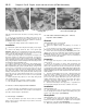
8.51 Crankshaft timing mark for
front cylinder
8.52a The longer nuts go on the front
cylinder head ...
8.52b ... and the front engine mounting
bracket fits on the studs
8.53 Install the oil baffle next to the front cylinder's cam sprocket,
facing in the direction shown
45 Turn the cam sprocket clockwise far enough to remove all slack in
the front run of the cam chain, but no farther. Insert a finger in the
tensioner hole and push against the chain damper. Make sure the
timing marks on the cam sprocket and crankshaft are aligned correctly
(see illustrations 8.6a and 8.6b).
46 With the marks correctly aligned, install the washer and cam
sprocket bolt and tighten to the torque listed in this Chapter's Specifi-
cations.
47 Install the cam chain tensioner (see Section 7).
48 Adjust the valve clearances (see Chapter 1).
49 Install the rocker arm covers with new O-rings.
50 Install the cam sprocket cover, using a new O-ring.
Front cylinder head
Refer to illustrations 8.51, 8.52a, 8.52b and 8.53
51 Repeat Steps 38 through 40 to install the front cylinder head,
noting that the slot in the timing rotor must be aligned with the
crankcase pointer when the camshaft dowel is aligned with the
cylinder head mark (see illustration).
52 Install the washers, cylinder head nuts and bolts and engine
mounting bracket (see illustrations).
53 Repeat Steps 42 through 51 to finish installing the cylinder head,
noting that there is an oil baffle on the sprocket (see illustration).
54 Install the ignition coils and their bracket (see Chapter 4).
Both cylinder heads
55 Change the engine oil (see Chapter 1).
56 The remainder of installation is the reverse of the removal steps.
9 Valves/valve seats/valve guides - servicing
1 Because of the complex nature of this job and the special tools
and equipment required, servicing of the valves, the valve seats and
the valve guides (commonly known as a valve job) is best left to a
professional.
2 The home mechanic can, however, remove and disassemble the
head, do the initial cleaning and inspection, then reassemble and
deliver the head to a dealer service department or properly equipped
motorcycle repair shop for the actual valve servicing. Refer to Section
8 for those procedure's.
3 The dealer service department will remove the valves and springs,
recondition or replace the valves and valve seats, replace the valve
guides, check and replace the valve springs, spring retainers and
keepers/collets (as necessary), replace the valve seals with new ones
and reassemble the valve components.
4 After the valve job has been performed, the head will be in like-
new condition. When the head is returned, be sure to clean it again
very thoroughly before installation on the engine to remove any metal
particles or abrasive grit that may still be present from the valve service
operations. Use compressed air, if available, to blow out all the holes
and passages.
10 Cylinder head and valves - disassembly, inspection
and reassembly
These procedures are the same as for XV535 models. Refer to
Part A of this Chapter for procedures and Part B for specifications.
11 Cylinders - removal, inspection and installation
Removal
Refer to illustrations 11.2, 11.3 and 11.4
1 Following the procedure given in Section 8, remove the cylinder
head.
2 Remove the cylinder bolts (see illustration).
3 Lift the cylinder straight up to remove it, supporting the cam chain
as you do so (see illustration). If it's stuck, tap around its perimeter
with a soft-faced hammer, taking care, not to break the cooling fins.
Don't attempt to pry between the cylinder and the crankcase, as you
will.ruin the sealing surfaces. As you lift, note the location of the dowel
pins and O-ring. Be careful not to let these drop into the engine.
4 Stuff clean shop towels around the pistons and remove the
gasket and all traces of old gasket material from the surfaces of the