
Service manual


CONTROL FUNCTIONS
1-10
GEN
INFO
NOTE:
• If an out-of-step indication takes place, mov-
ing the main switch to “OFF” once and then
to “RUN”, brings the tachometer back to a
normal indication through its corrective
action.
• There is no functional problem involved with
the out-of-step indication, which can be
brought back to a normal indication through
the corrective action of the tachometer.
EC15B010
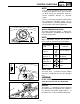
WATER TEMPERATURE GAUGE
The water temperature gauge 1 displays dif-
ferent indications according to the change in
the water temperature.
NOTE:
Water temperature may be 70 ˚C (158 ˚F)
when engine is operated in good conditions.
Cooling water
Display Conditions
temp.
~19 ˚C
“LO” is display.
(~66 ˚F)
20~119 ˚C Temperature is
(68~247 ˚F) displayed.
120~140 ˚C Temperature
(248~284 ˚F) flash.
141 ˚C~ Message “HI”
(285 ˚F~) flash.
EC15F000
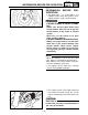
VALVE JOINT
This valve joint 1 prevents fuel from flowing
out and is installed to the fuel tank breather
hose.
CC
CAUTION:
In this installation, make sure the arrow
faces the fuel tank and also downward.
EC15X000
BATTERY
The battery 1 is provided as power supply for
the electric parts. Except when the machine is
run, disconnect the power supply coupler 2 of
the wireharness to prevent battery discharge.