
Owner's Manual


SWP1 Owner’s Manual
14
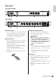
Status Indicator Display
The status indicators show different things depending on
the LED mode setting.
LINK/ACT setting
The status indicators show each port’s link status and
connection status.
STATUS setting
The status indicators show the loop-related port’s status.
VLAN setting
The status indicators show the VLAN ID and trunk.
If DIP switch 1 is upward ([DANTE]), VLAN 1 is shown by
the upper indicator and the lower indicator unlit. VLAN 2
is shown by the upper indicator lit green and the lower
indicator unlit. Trunk is shown by upper and lower
indicators lit orange.
–: Unlit
G: Lit green
O: Lit orange
Note
• If a number of VLANs that cannot be completely displayed
above is specified, the upper and lower indicators ar
e lit
gr
een.
• If multiple VLAN IDs are specified for the same port, t
he
upp
er and lower indicators are lit orange.
OFF setting
All status indicators are unlit.
Initializing the SWP1
Here’s how to initialize the SWP1’s internal memory,
restoring it to the factory settings.
1. Power-off the SWP1.
2. While pressing and holding down the [LED
MODE]
button, then power-on the SWP1.
3. The [STATUS] indicator and the [OFF]
indicator lit and all status indicators li
t
or
ange, release the [LED MODE] button.
Initialization completed, The SWP1 will automatically
restart.
CAUTION
Do not turn off the power to the SWP1 during initialization.
Otherwise, a malfunction may occur.
NOTE
If initialization failed, contact Yamaha service personnel.
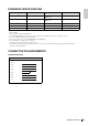
Indicator Illumination Status
Upper
Lit green Link is established. (LINK)
Flashing
green
Data is being transferred.
(ACT)
Unlit Link is lost.
Lower
Lit green Connected with 1000BASE-T.
Lit orange Connected with 100BASE-TX.
Unlit Connected with 10BASE-T.
Indicator Illumination Status
Upper
and lower
Flashing
orange
Loop was detected, and
communication is halted.
Unlit
Loop not detected. Or loop
was detected, but
communication is not halted.
Indicators
1
VLAN ID low high
Trunk
Upper – GO – – GO O
Lower – – – G O O G O